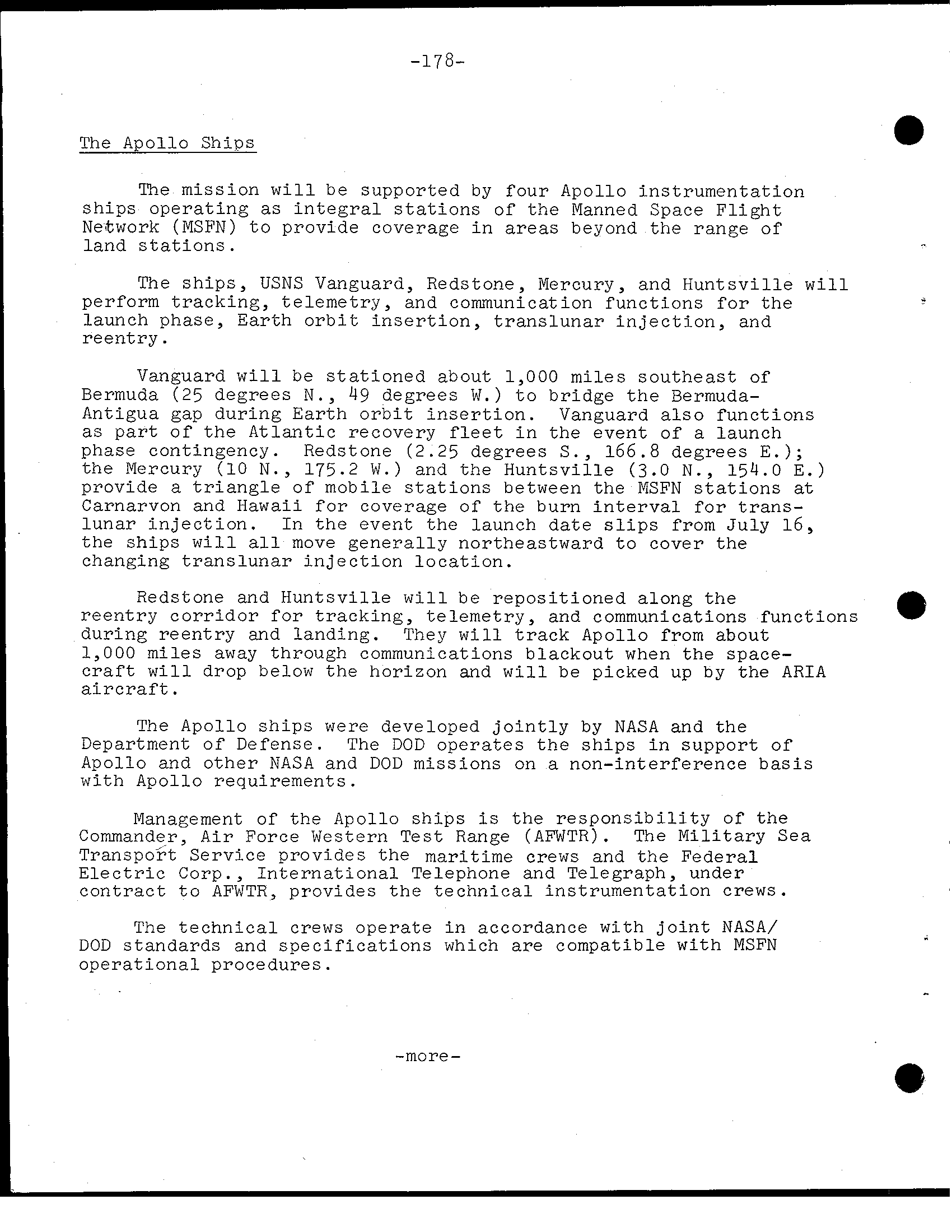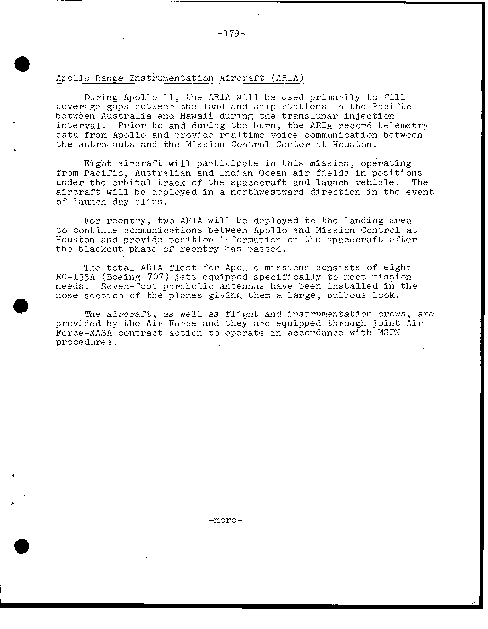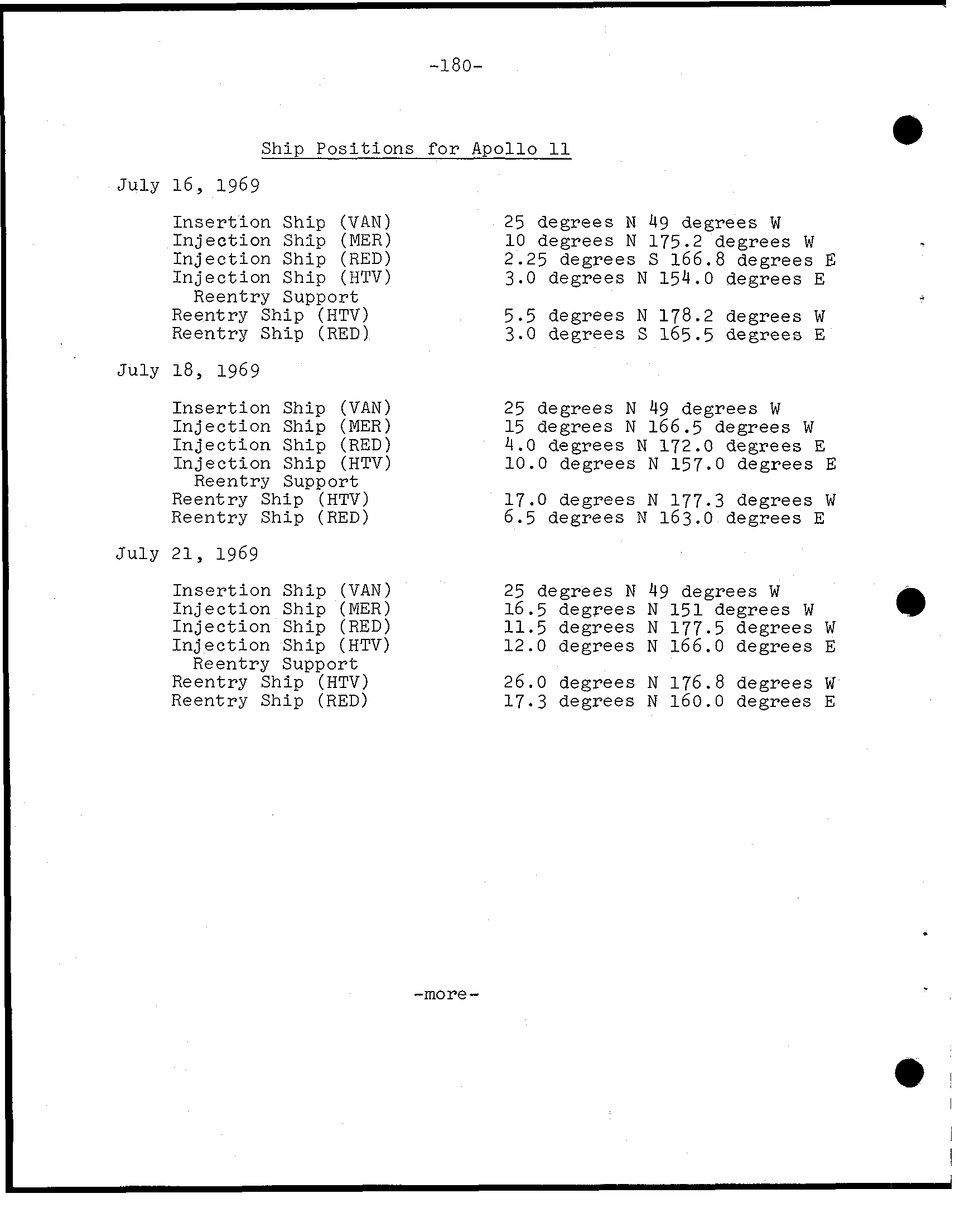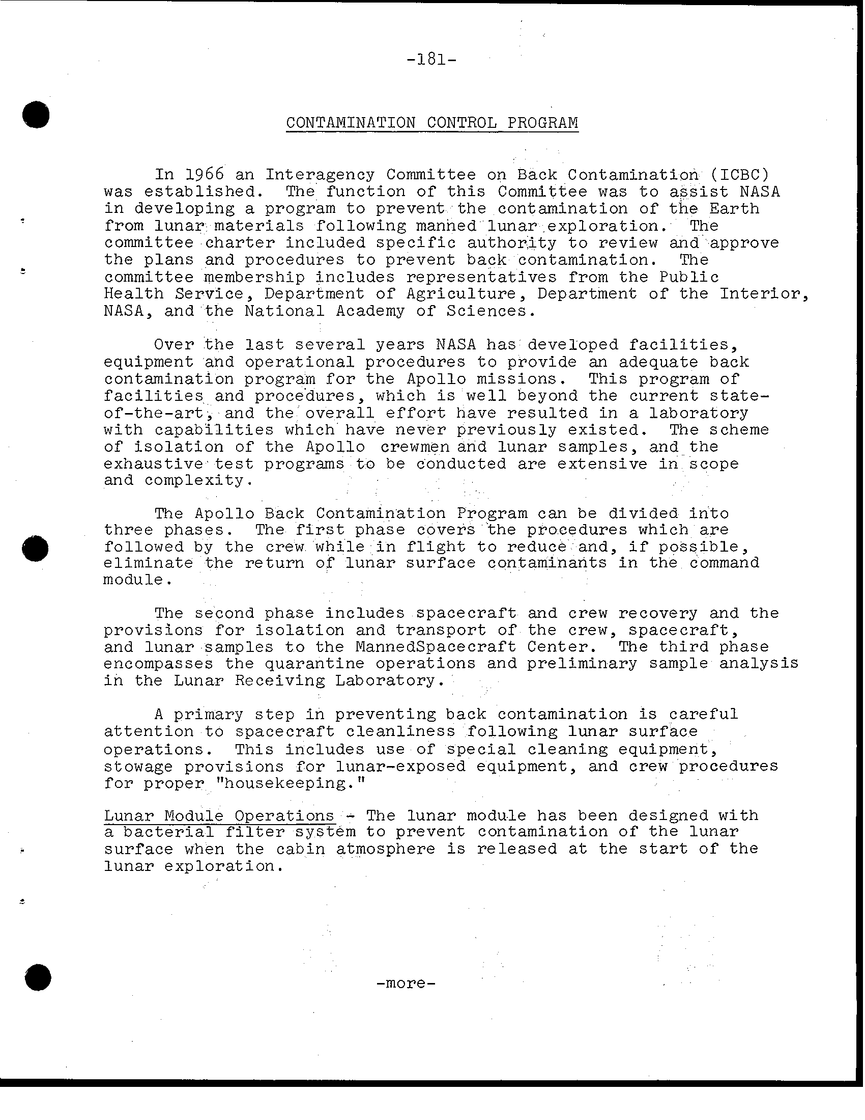
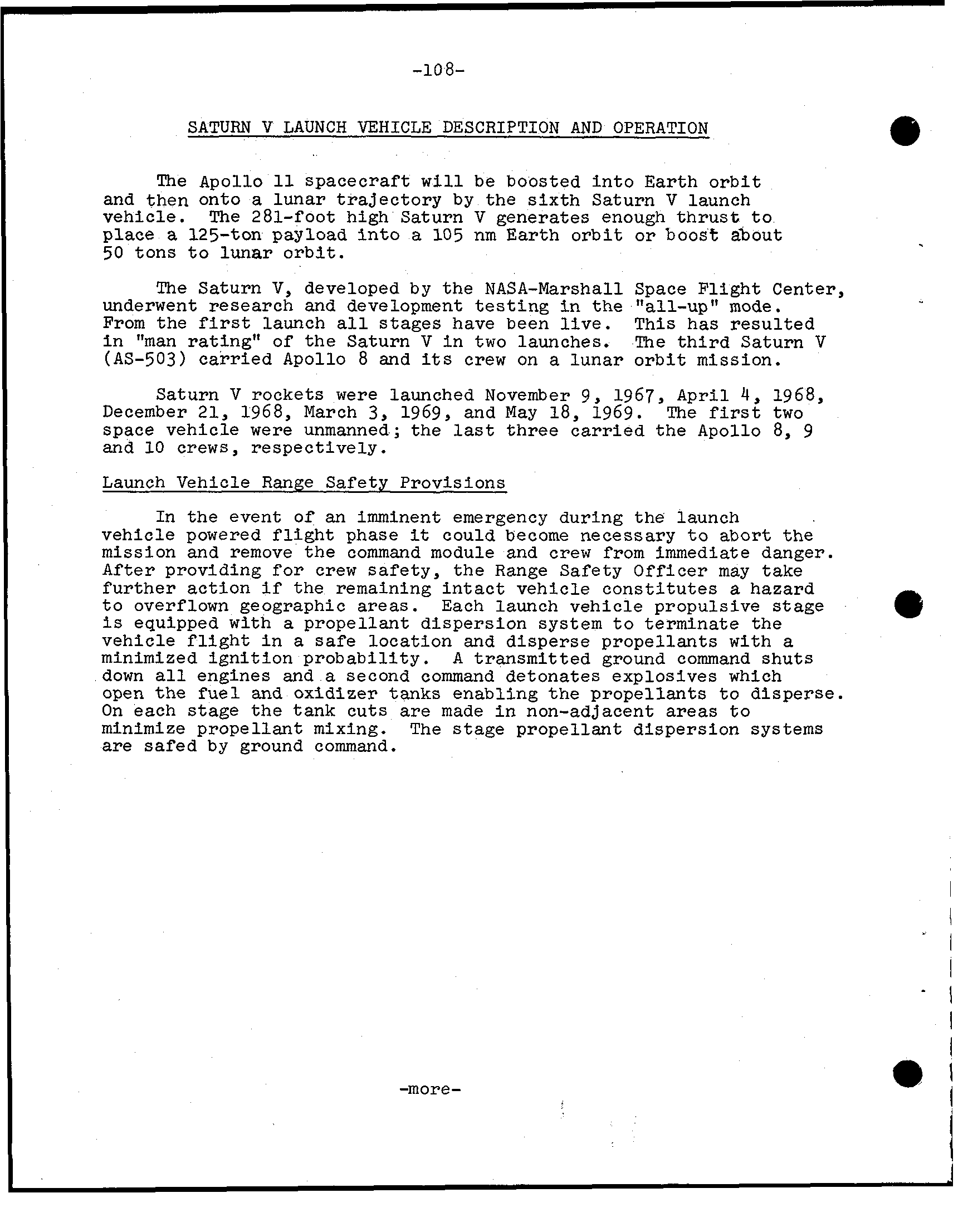
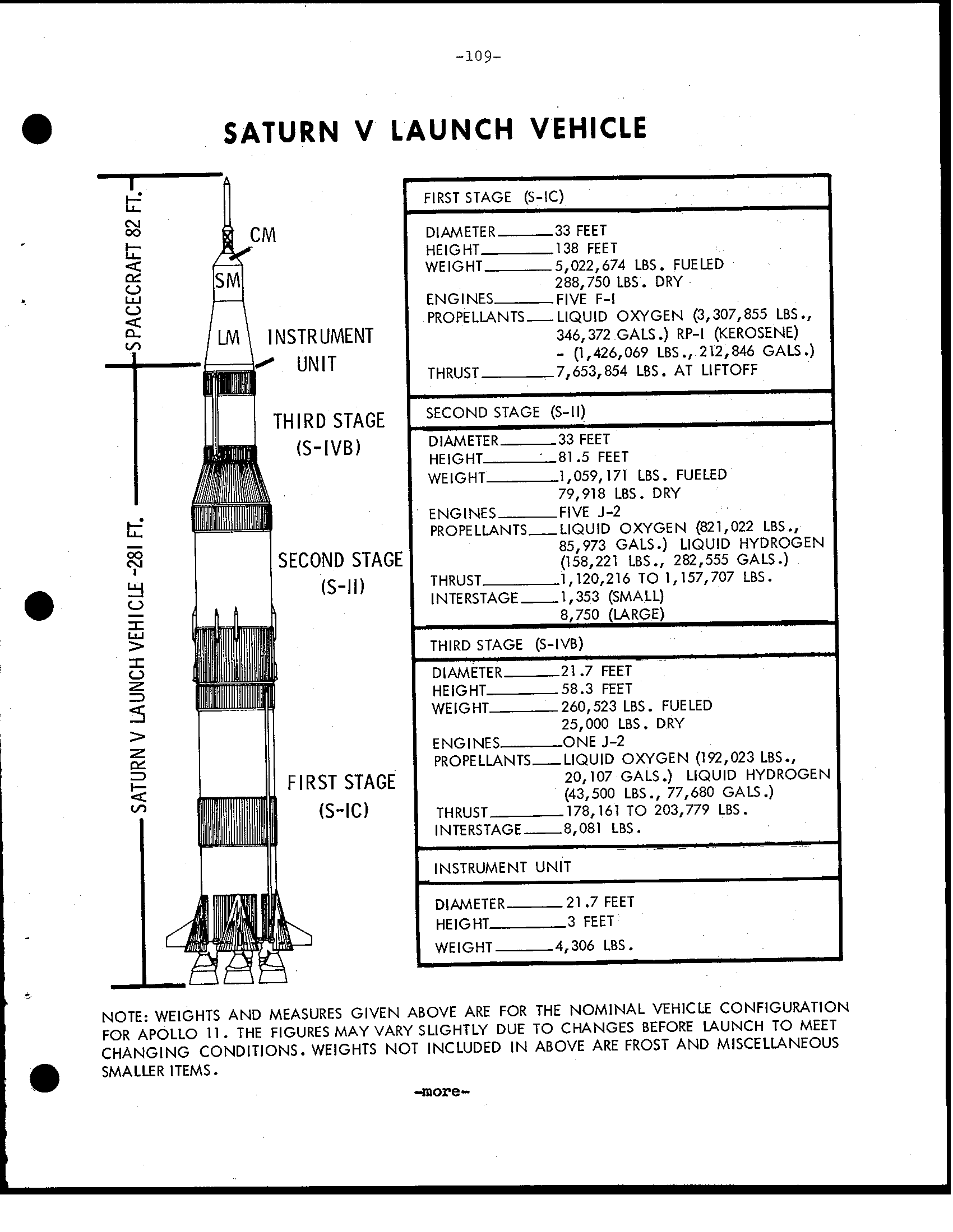
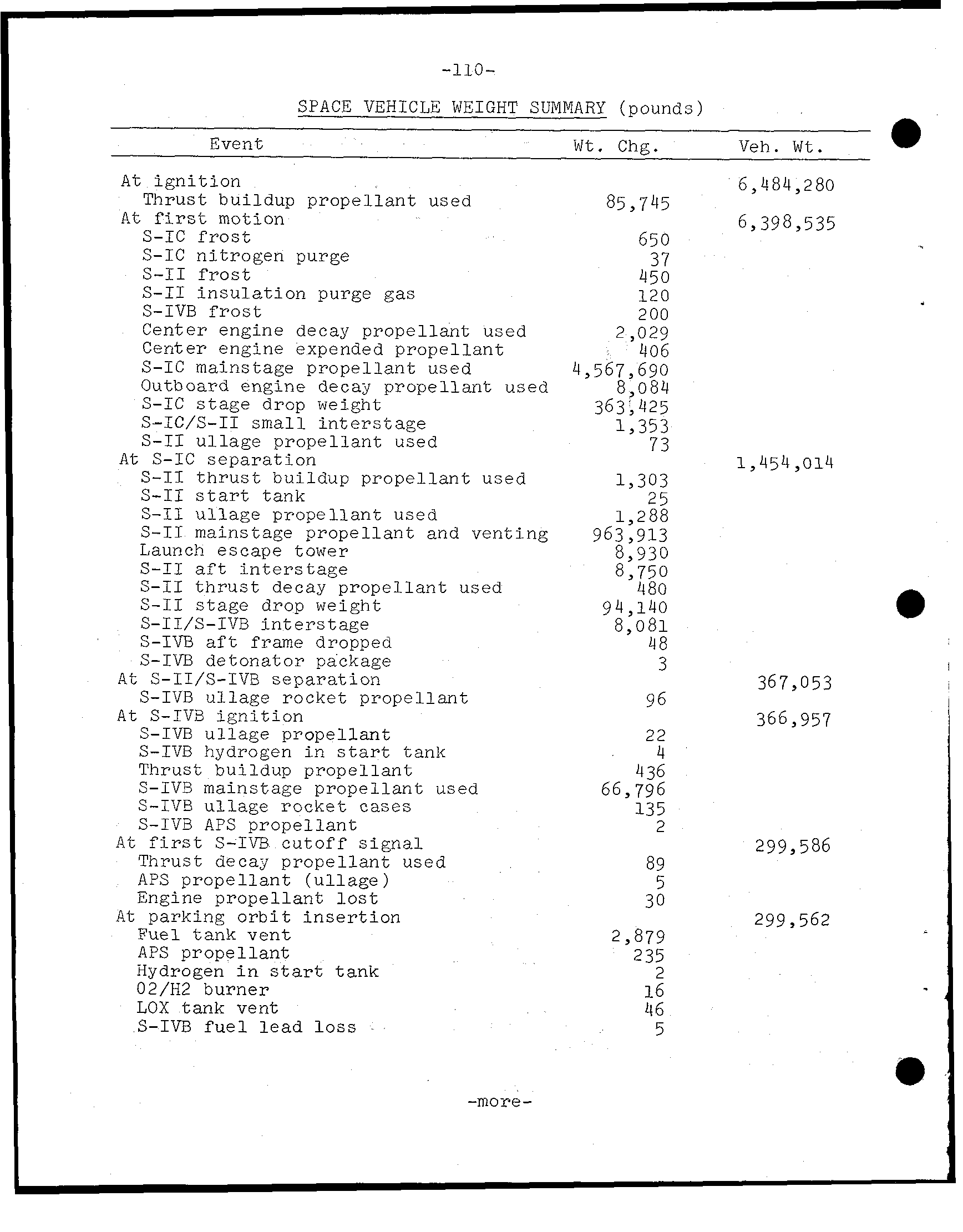
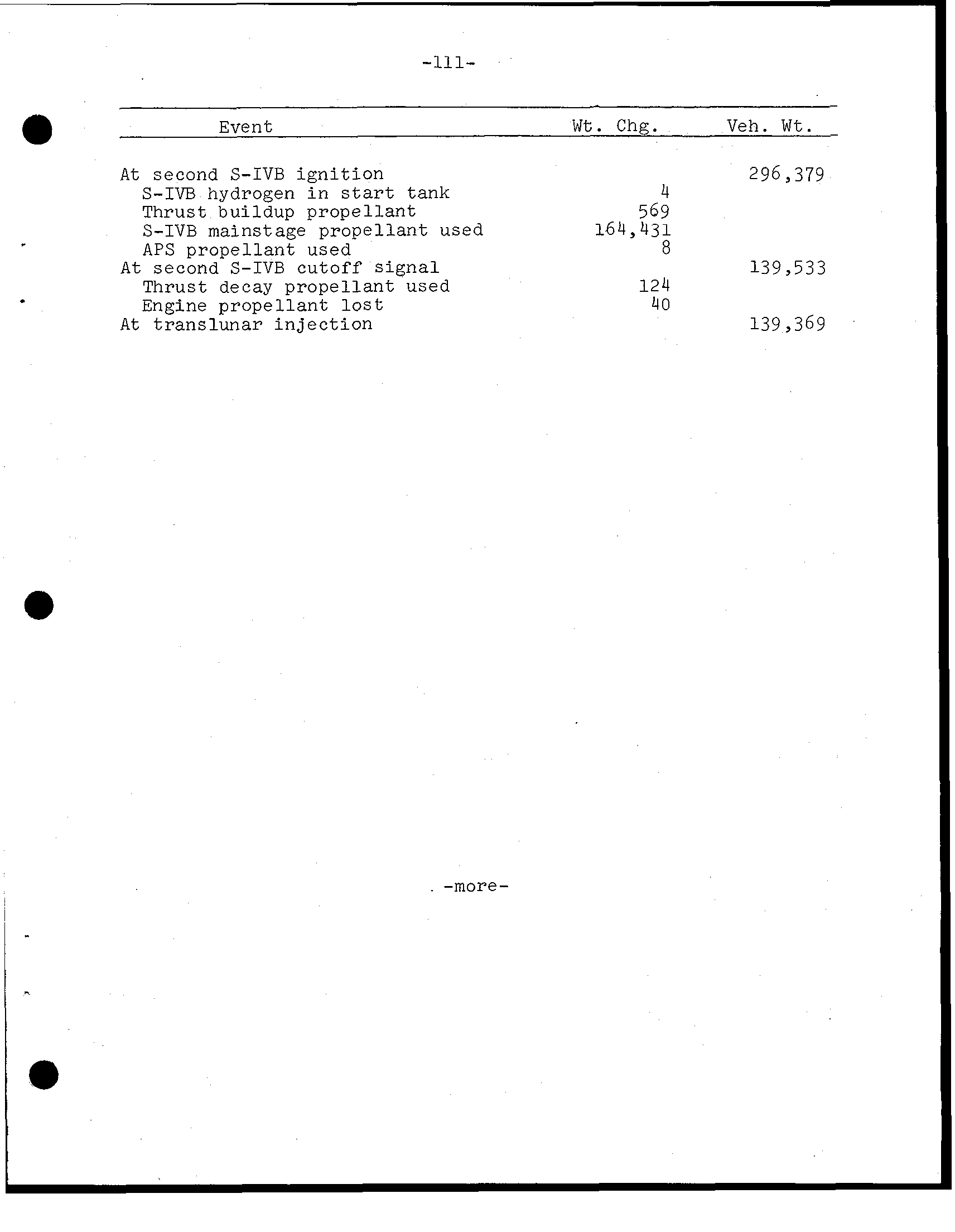
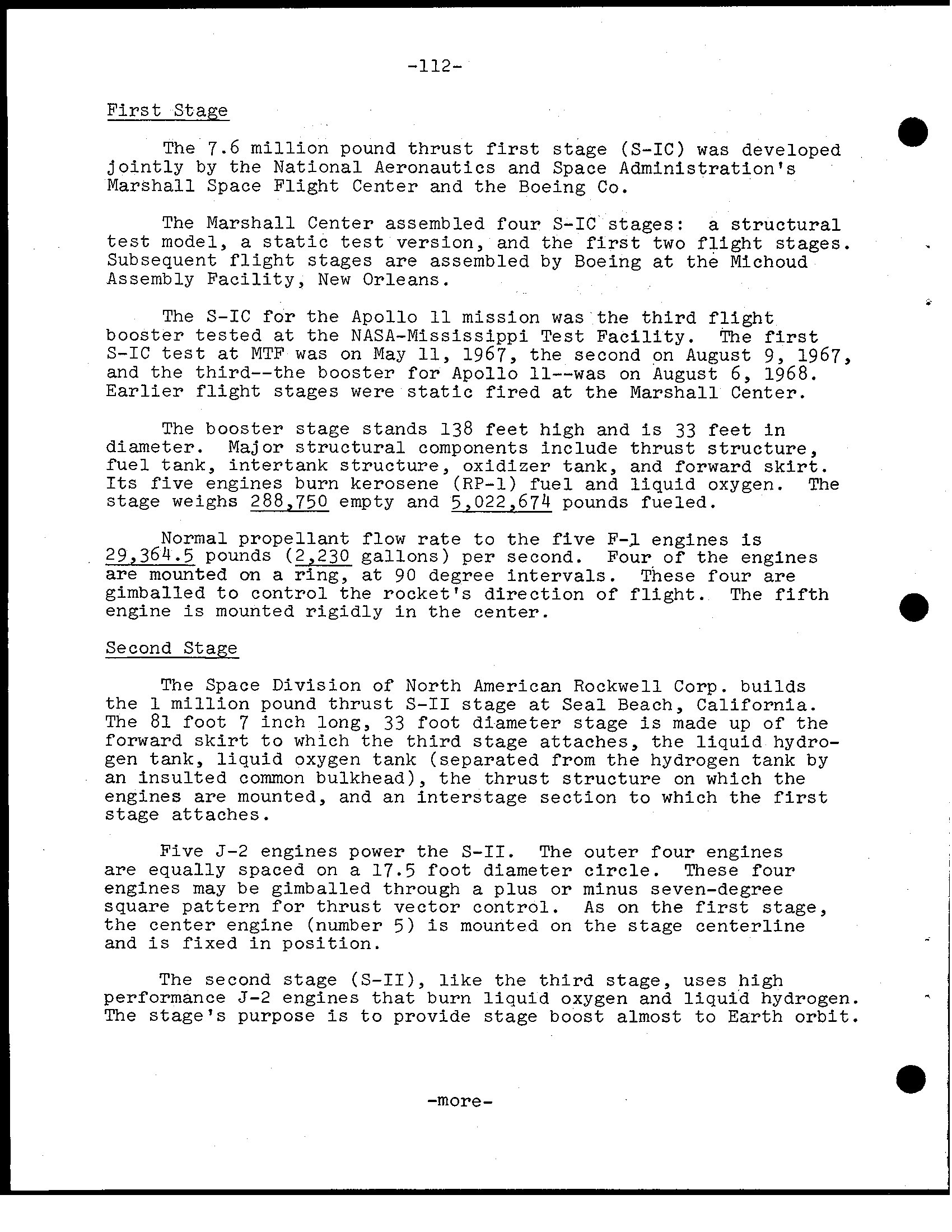
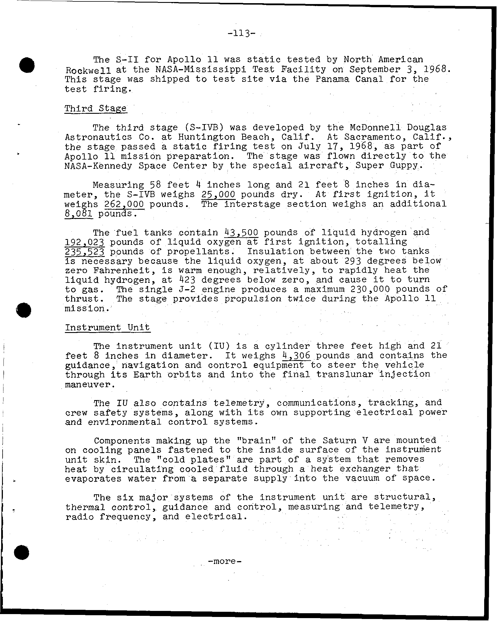
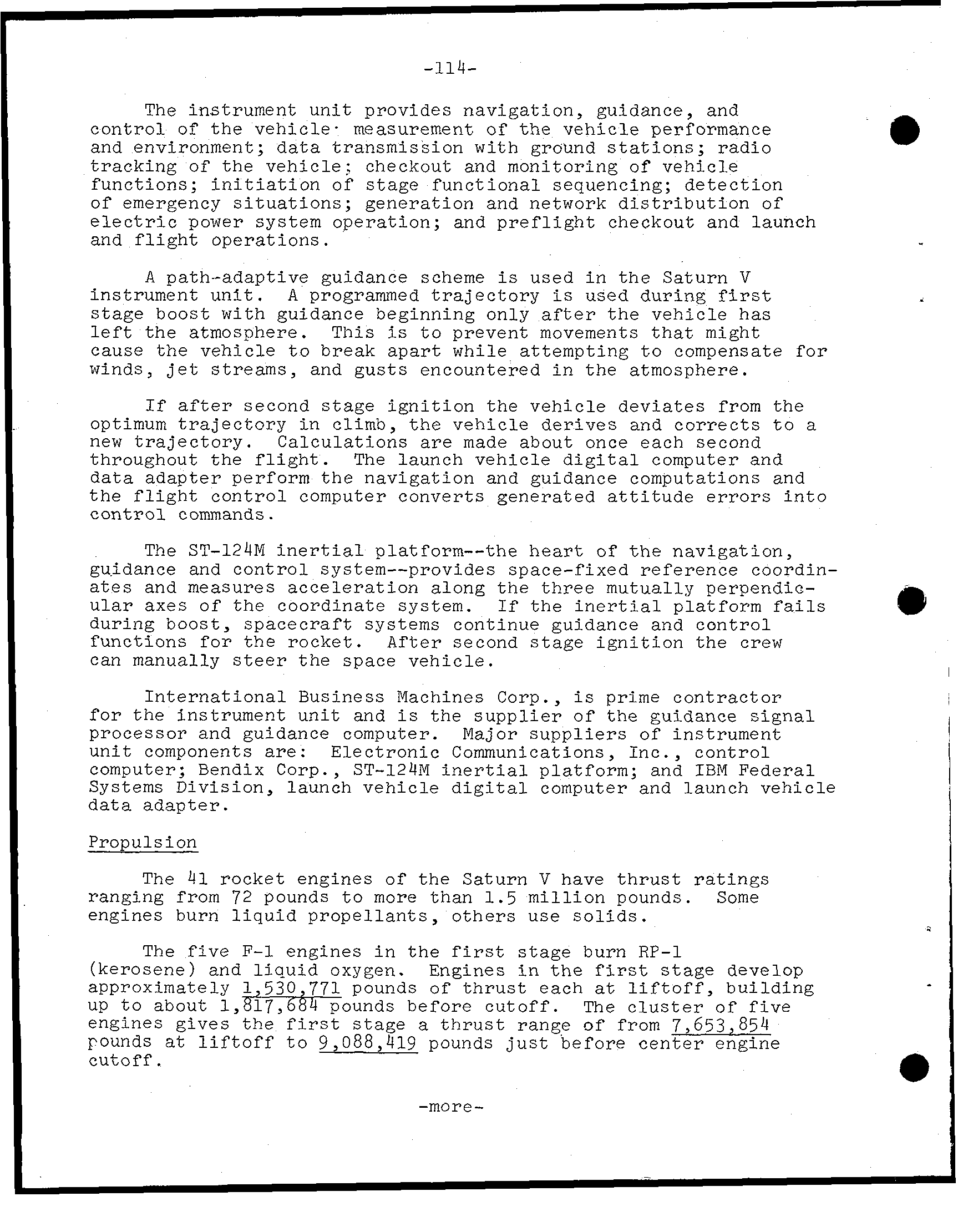
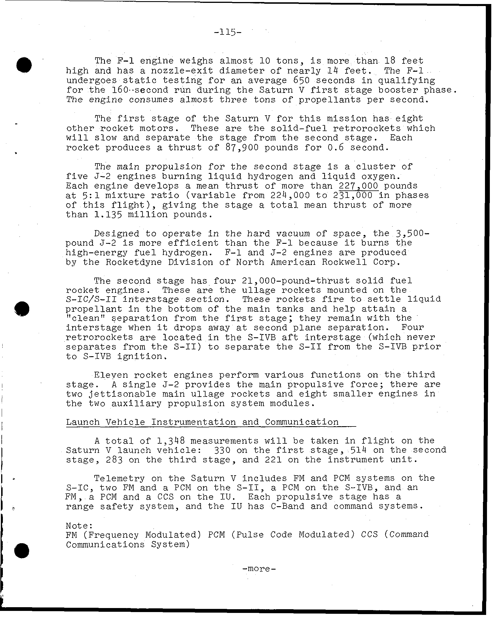
P R E S S a K I T APOLLO 11 LUNAR LANDING MISSION * ' N A T I O N A L A E R O N A U T I C S A N D SPACE A D M I N I S T R A T I O N
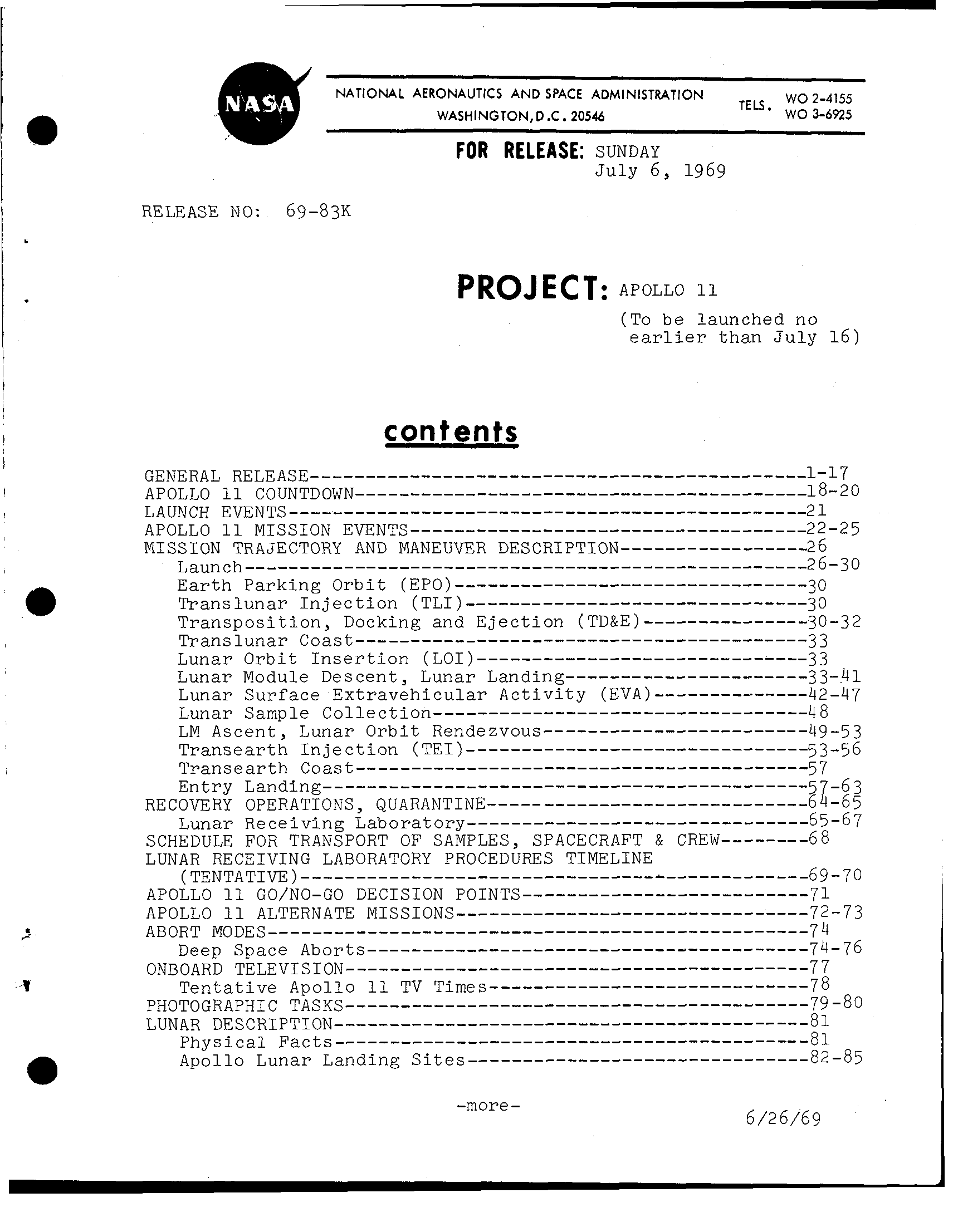
NATIONAL AERONAUTICS AND SPACE ADMINISTRATION WO 2-4155 WASHINGT0N.D.C. 20546 TELS* WO 3-6525 FOR RELEASE: SUNDAY J u l y 6, 1969 RELEASE NO: 69-83K (To b e launched no e a r l i e r t h a n July 16) -more- 6/26/69
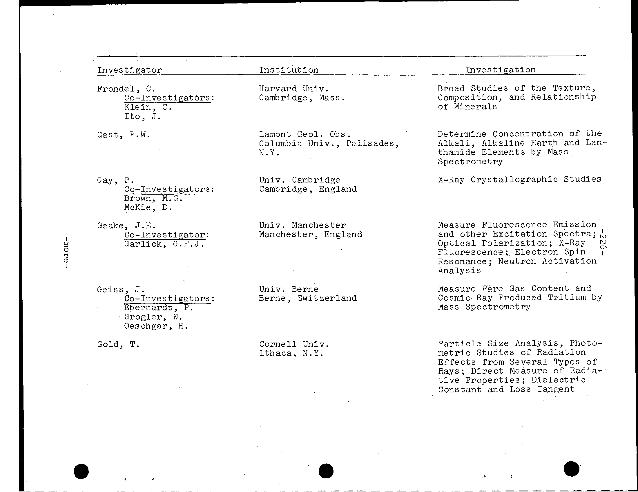
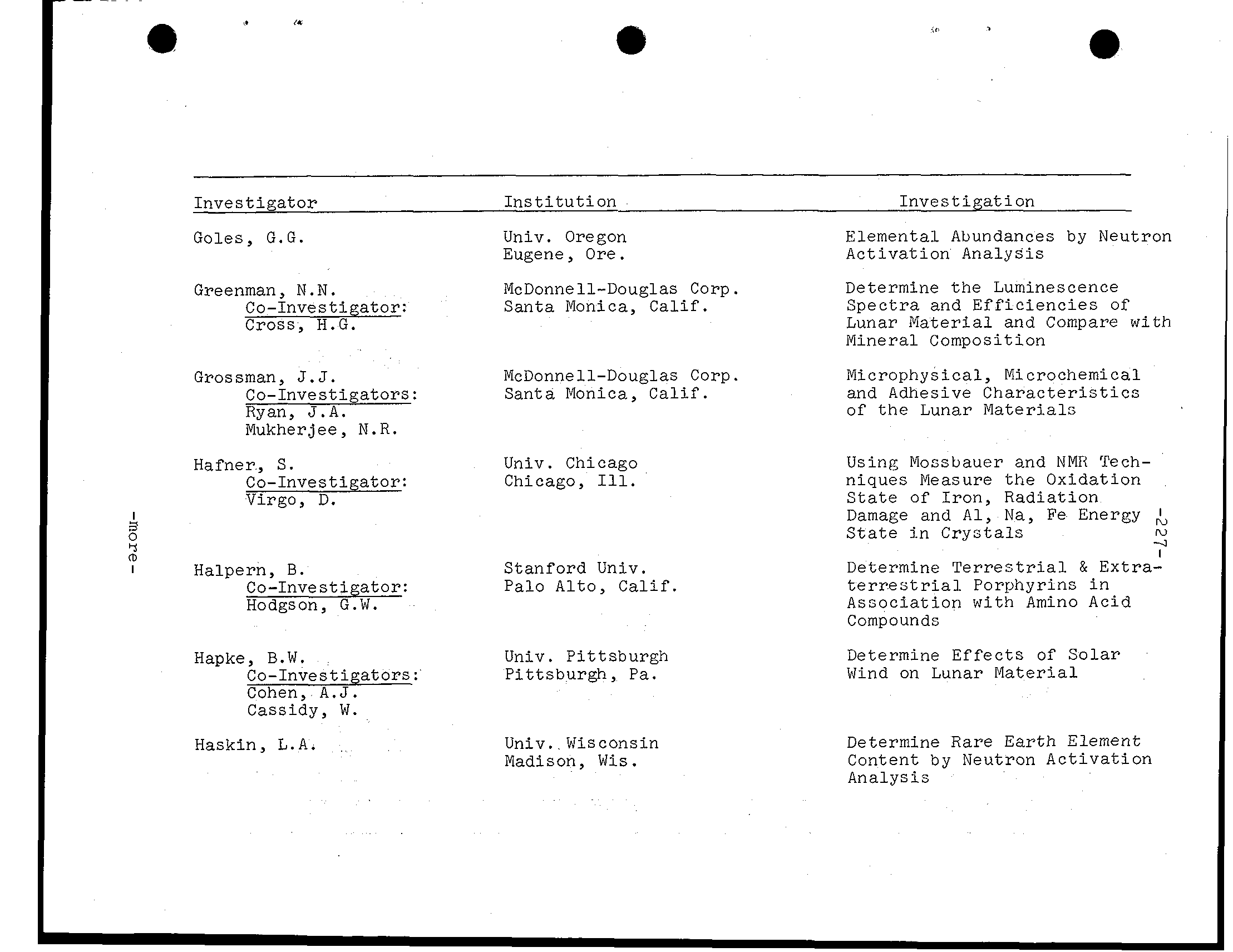
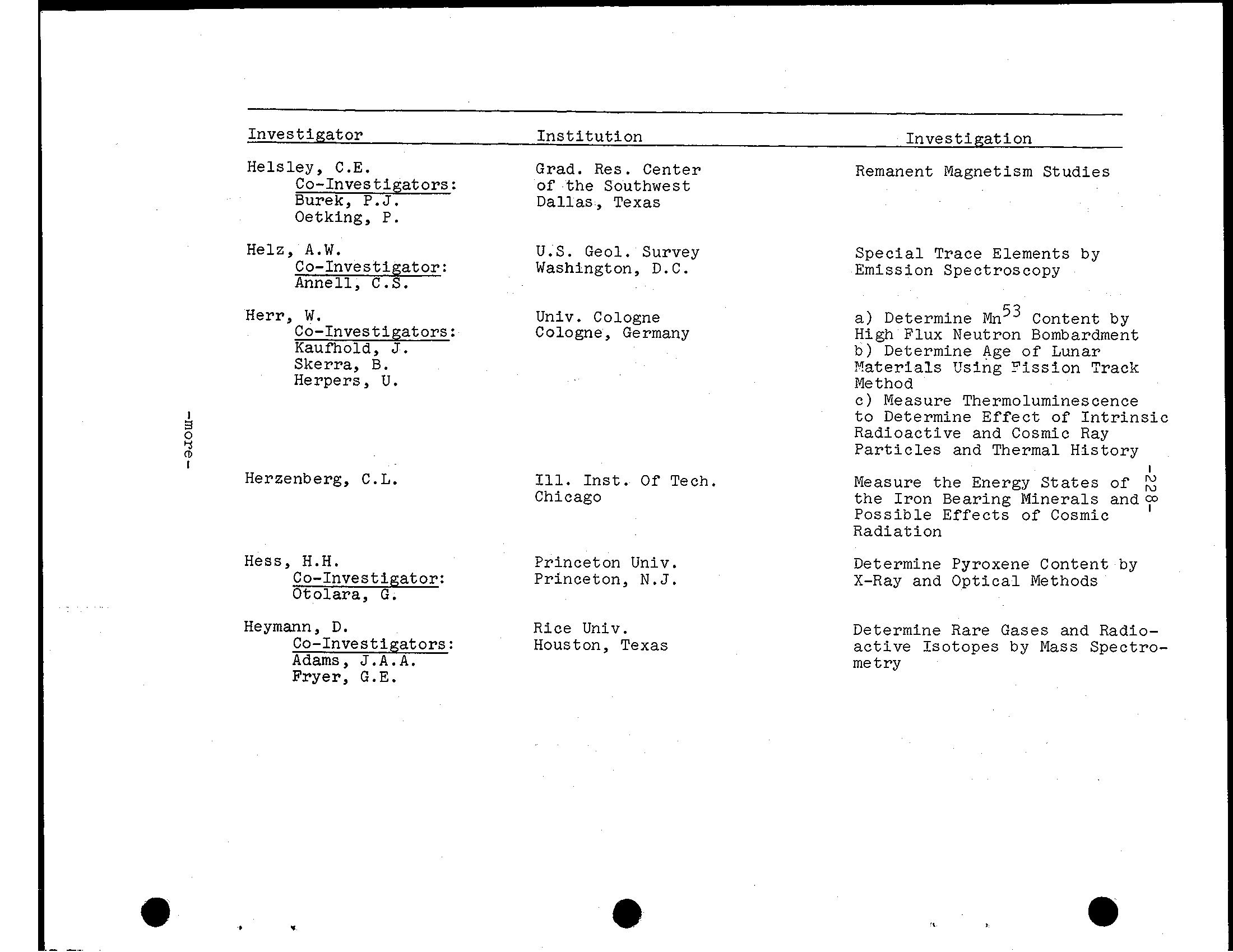
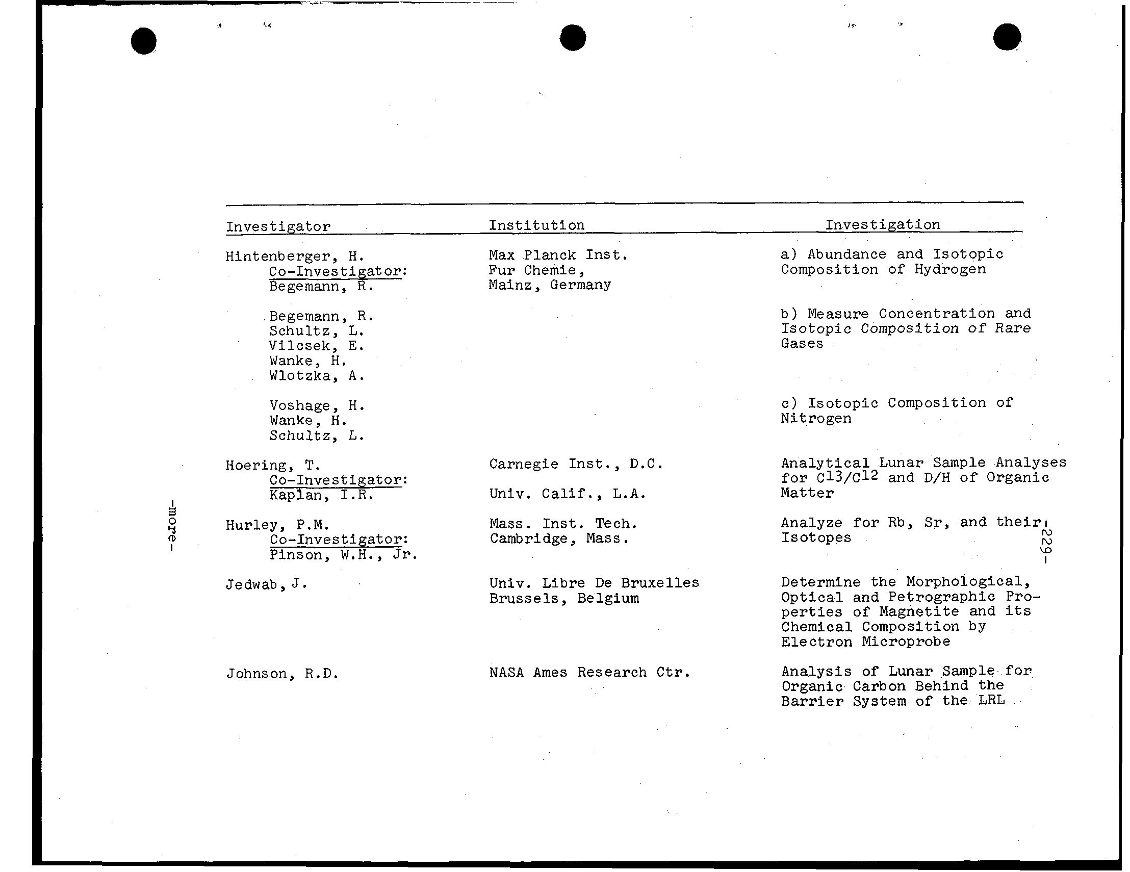
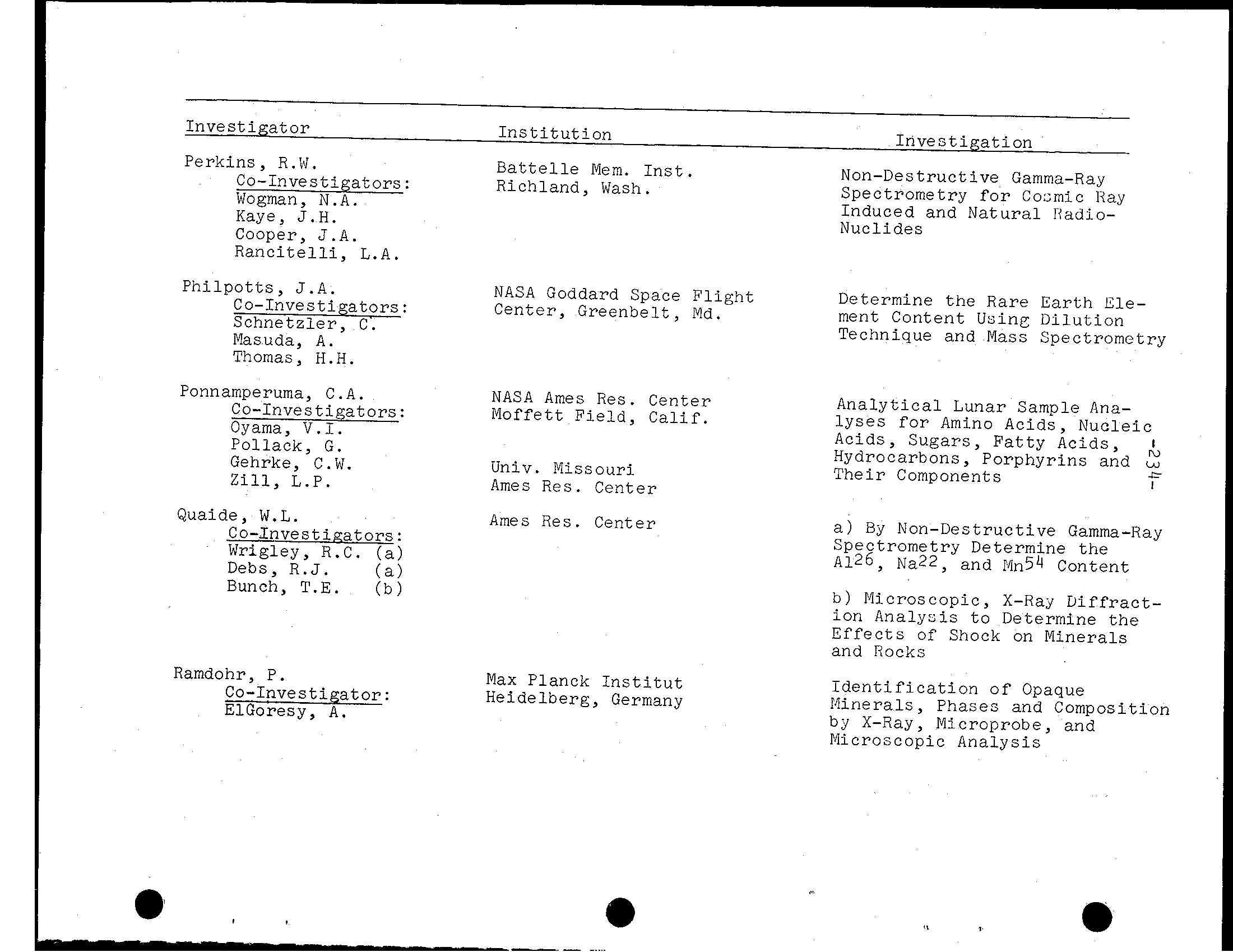
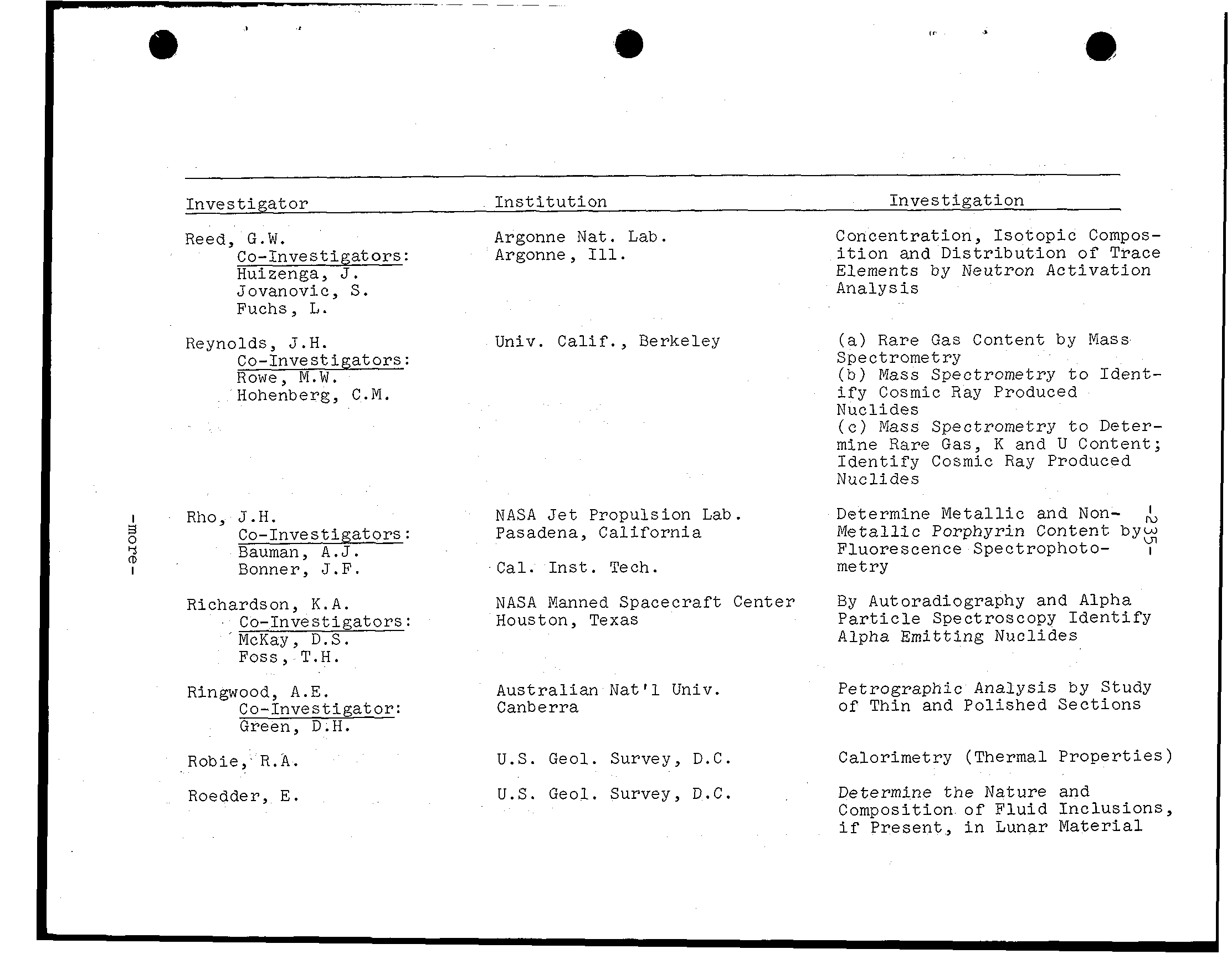
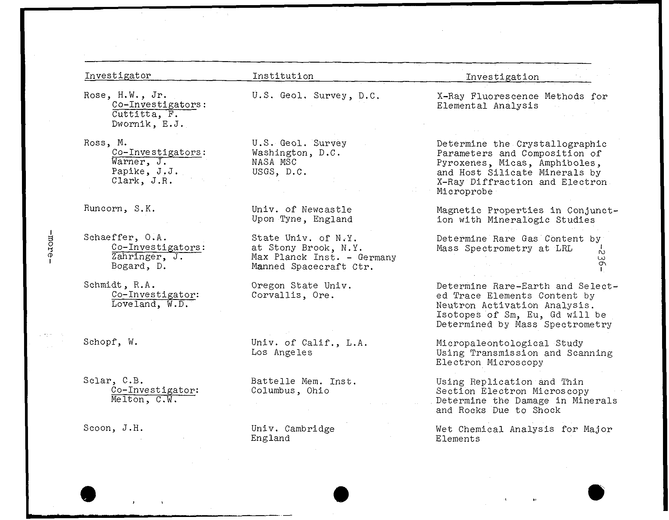
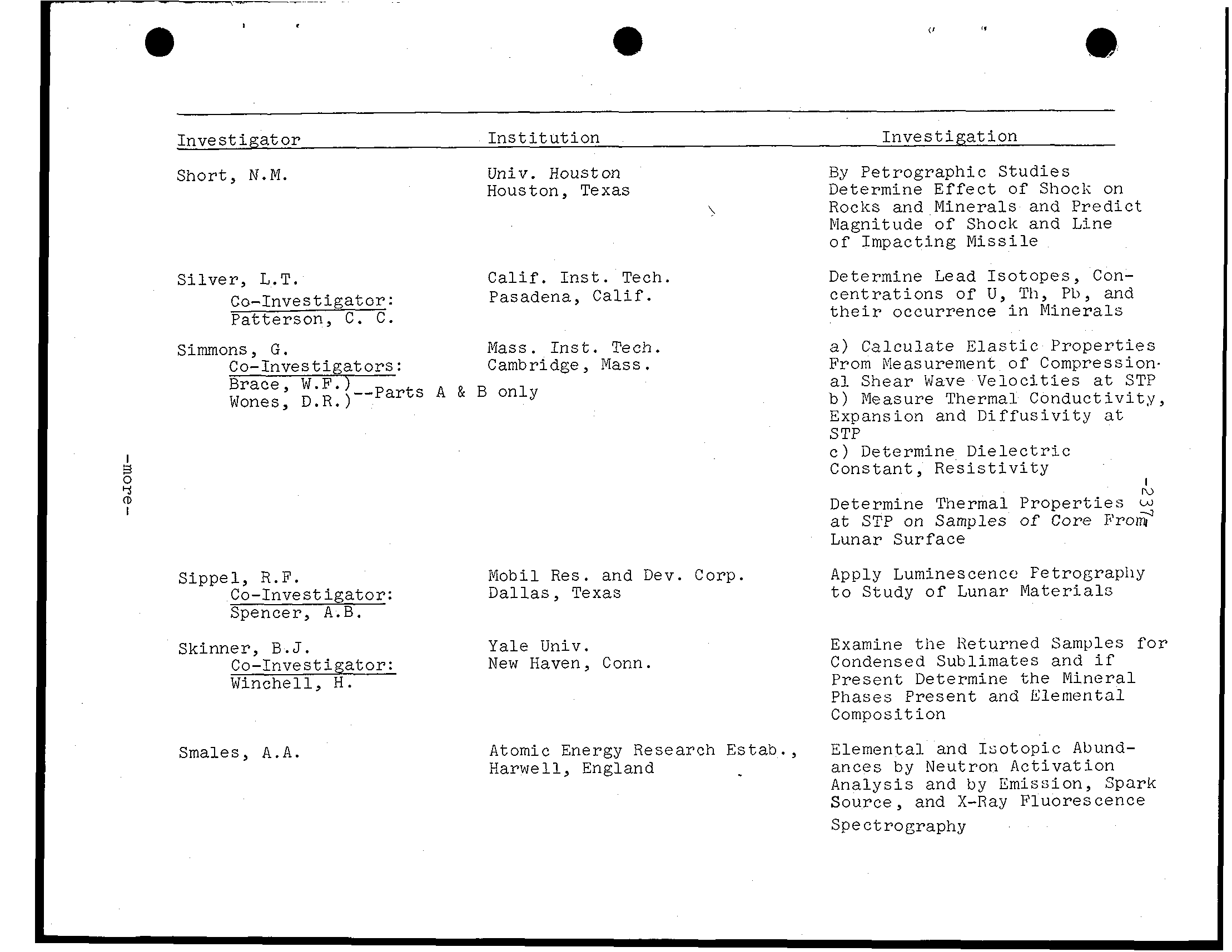
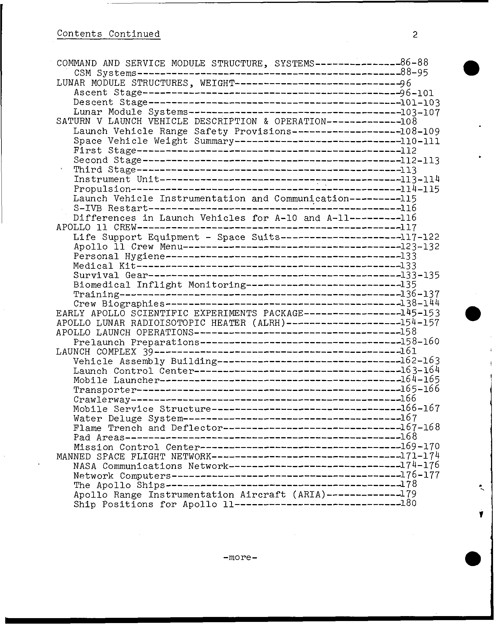
Contents Continued 2 I -more-
Contents Continuea 3 - 0 -
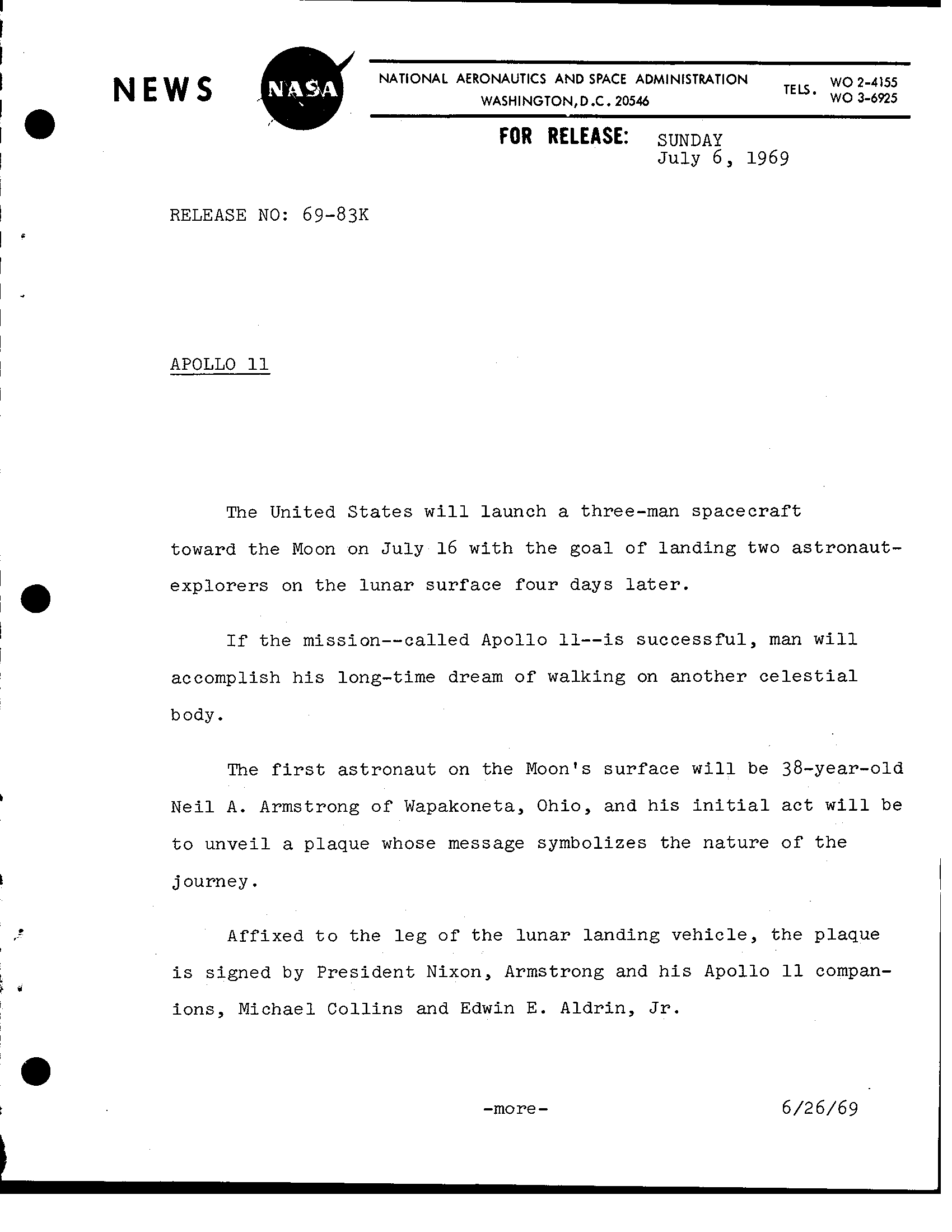
’. NATIONAL AERONAUTICS AND SPACE ADMINISTRATION N E W S WO 2-4155 WASHINGTON,D.C. 20546 TELS* W03-6925 I FOR RELEASE: SUNDAY July 6, 1969 I RELEASE NO: 69-839 I S APOLLO The United S t a t e s w i l l launch three-man spacecraft toward t h e Moon on July 16 with t h e goal of landing two astronaut- explorers on the lunar surface four days t h e mission--called Apollo successful, man w i l l accomplish h i s long-time dream of walking on another body. The first astronaut on the Moon’s surface w i l l 38-year-old Neil A. Armstrong of Wapakoneta, Ohio, and h i s i n i t i a l a c t w i l l be t o unveil plaque whose symbolizes the nature of t h e . journey Affixed to the l e g of the lunar landing vehicle, the plaque signed b y President Nixon, Armstrong and h i s Apollo compan- L ions, Michael Collins and Edwin E. Aldrin, - -more 6/26/69
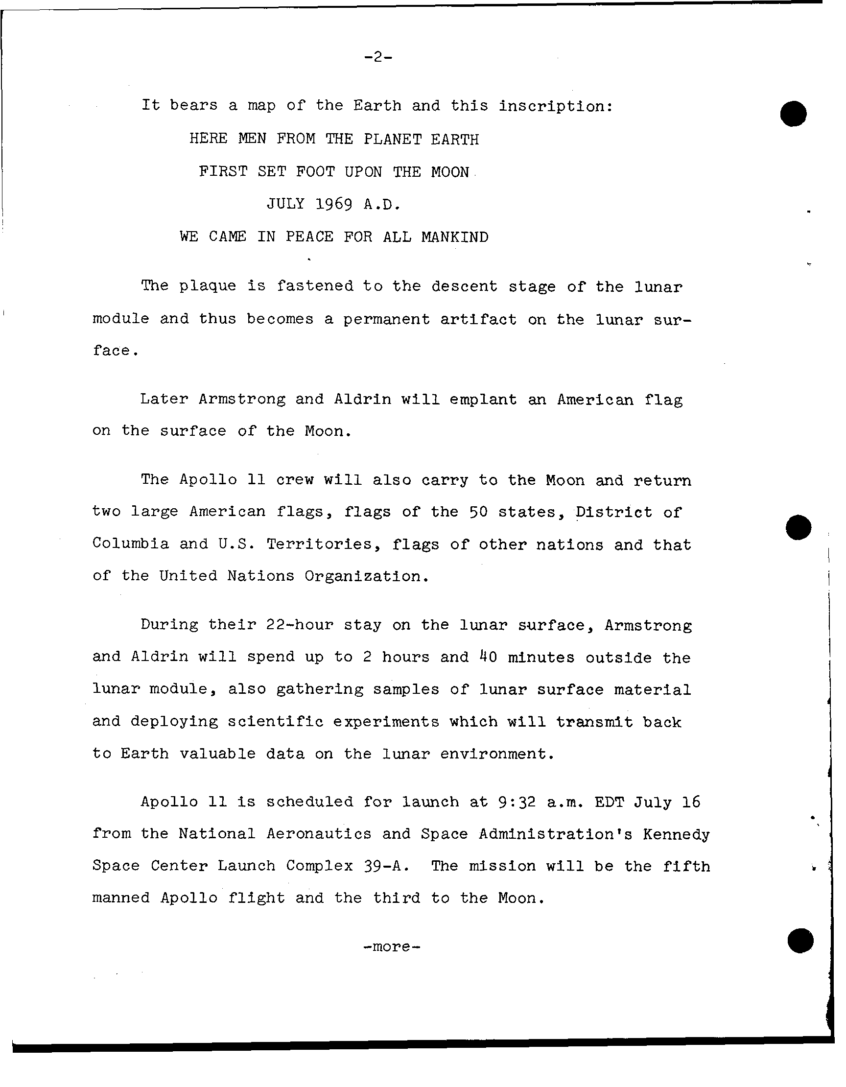
-2- bears map o f the E a r th and t h i s inscription: HERE MEN FROM THE PLANET EARTH FIRST SET FOOT UPON THE MOON J U L Y 1969 A.D. WE CAME I N PEACE FOR ALL MANKIND plaque fastened t o descent stage of lunar module and thus becomes permanent on the sur- face. Armstrong and Aldrin w i l l emplant American f l a g on the surface of Moon. The Apollo crew w i l l a l s o carry t o Moon and r e t u r n two large American f l a g s of the 50 D i s t r i c t of Columbia and U.S. T e r r i t o r i e s, f l a g s of other nations and t h a t of the United Nations Organization. During t h e i r 22-hour s t a y on t h e lunar surface, Armstrong and Aldrin w i l l spend up t o 2 hours and 40 minutes outside lunar module, a l s o gathering samples o f lunar surface material and deploying s c i e n t i f i c experiments which w i l l transmit back t o E a r t h valuable data on the lunar environment. Apollo scheduled f o r launch 9:32 a.m. EDT July 16 from the National Aeronautics and Space Administration's Kennedy Space Center Launch Complex 39-A. The mission w i l l be the f i f t h manned Apollo f l i g h t and the t h i r d t o t h e Moon. -more-
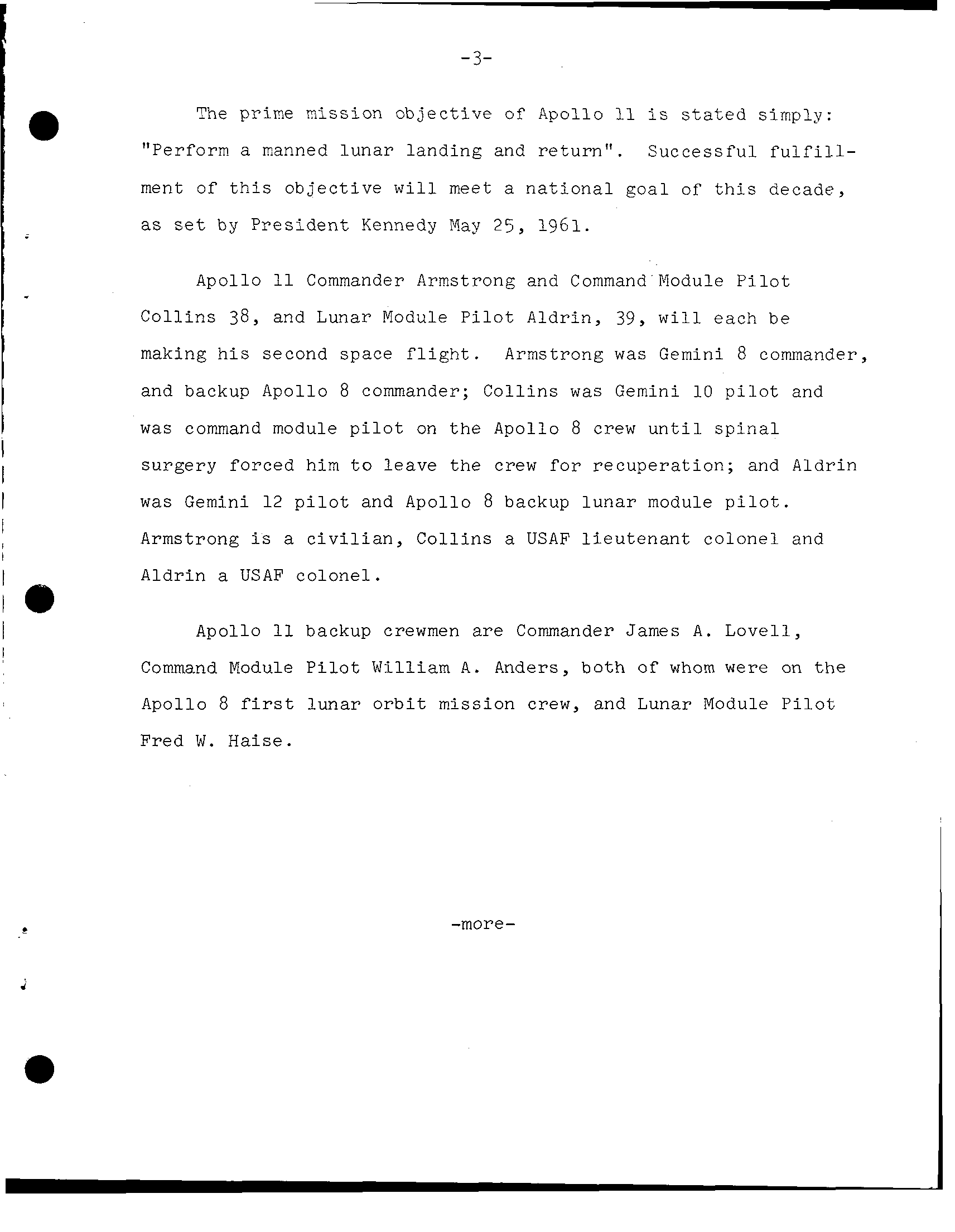
3- a The prime mission o b j e c t i v e of Apollo s t a t e d simply: "Perform manned l u n a r landing and r e t u r n". S u c c e s s f u l f u l f i l l - ment of t h i s o b j e c t i v e w i l l meet a n a t i o n a l g o a l of t h i s decade, as set by P r e s i d e n t Kennedy May 2 5, 1961. Apollo Commander Armstrong and Command Module P i l o t C o l l i n s 38, and Lunar Module P i l o t Aldrin, 39, w i l l each be making h i s second space f l i g h t. Armstrong was Gemini 8 commander, and backup Apollo 8 commander; C o l l i n s was Gemini 1 0 p i l o t and was command module p i l o t on t h e Apollo 8 crew u n t i l s p i n a l I surgery forced him t o l e a v e the crew f o r r e c u p e r a t i o n; and Aldrin I I was Gemini 12 p i l o t and Apollo 8 backup l u n a r module p i l o t. I Armstrong a c i v i l i a n, C o l l i n s a USAF l i e u t e n a n t colonel and I I Aldrin USAF colonel. la I Apollo backup crewmen are Commander A. L o v e l l, I Command Module P i l o t W i l l i a m A. Anders, both of whom were on t h e Apollo 8 l u n a r o r b i t mission crew, and Lunar Module P i l o t Fred W. -more-
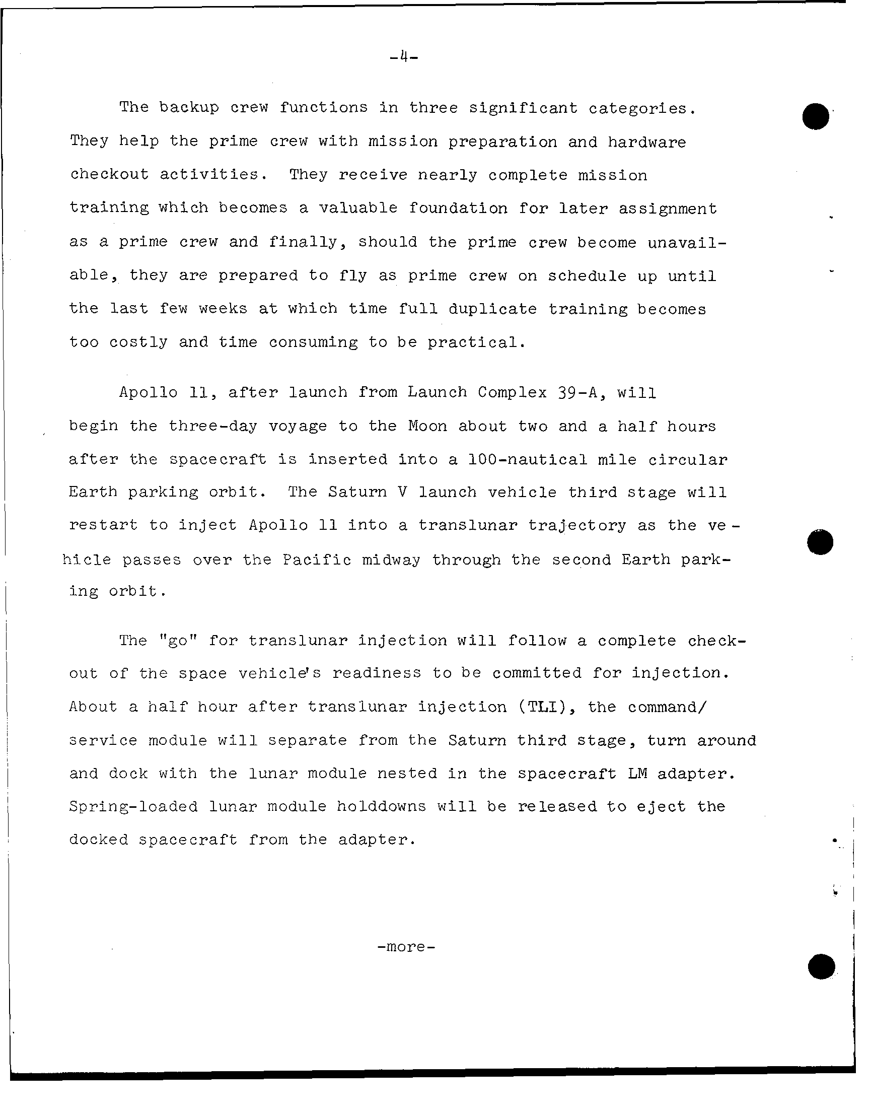
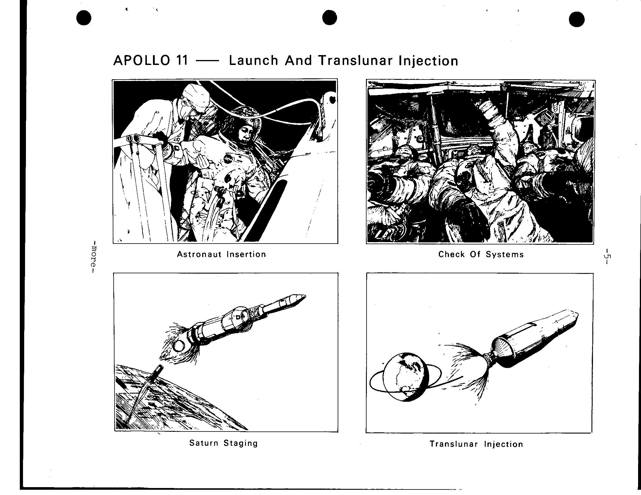
The backup crew functions i n three s i g n i f i c a n t categories. They help the prime crew with mission preparation and hardware checkout a c t i v i t i e s. They receive nearly complete mission t r a i n i n g which becomes a valuable foundation f o r assignment a prime crew and f i n a l l y, should the prime crew become unavail- they are prepared t o f l y as prime crew on schedule up u n t i l t h e few weeks which t i m e full duplicate t r a i n i n g becomes too costly and time consuming t o b e p r a c t i c a l. Apollo launch from Launch Complex 39-A, w i l l begin the three-day voyage t o the Moon about two and half hours a f t e r the spacecraft inserted i n t o 100-nautical mile c i r c u l a r E a r t h parking o r b i t. The Saturn V launch vehicle t h i r d stage w i l l r e s t a r t to i n j e c t Apollo i n t o a translunar t r a j e c t o r y the ve- h i c l e passes over the Pacific midway through t h e second Earth park- ing o r b i t. The for translunar i n j e c t i o n w i l l follow complete check- out of t h e space vehicle's readiness t o be committed for i n j e c t i o n. About h a l f hour a f t e r translunar i n j e c t i o n (TLI), the command/ service module w i l l separate from the Saturn t h i r d stage, turn around and dock w i t h the lunar module nested i n the spacecraft LM adapter. Spring-loaded l u n a r module holddowns w i l l released t o e j e c t the docked spacecraft from the adapter. ; I I I -more-
< e e APOLLO 11 Launch And Translunar Injection s Astronaut Insertion Check Of Systems (D I Saturn Staging Translunar Injection
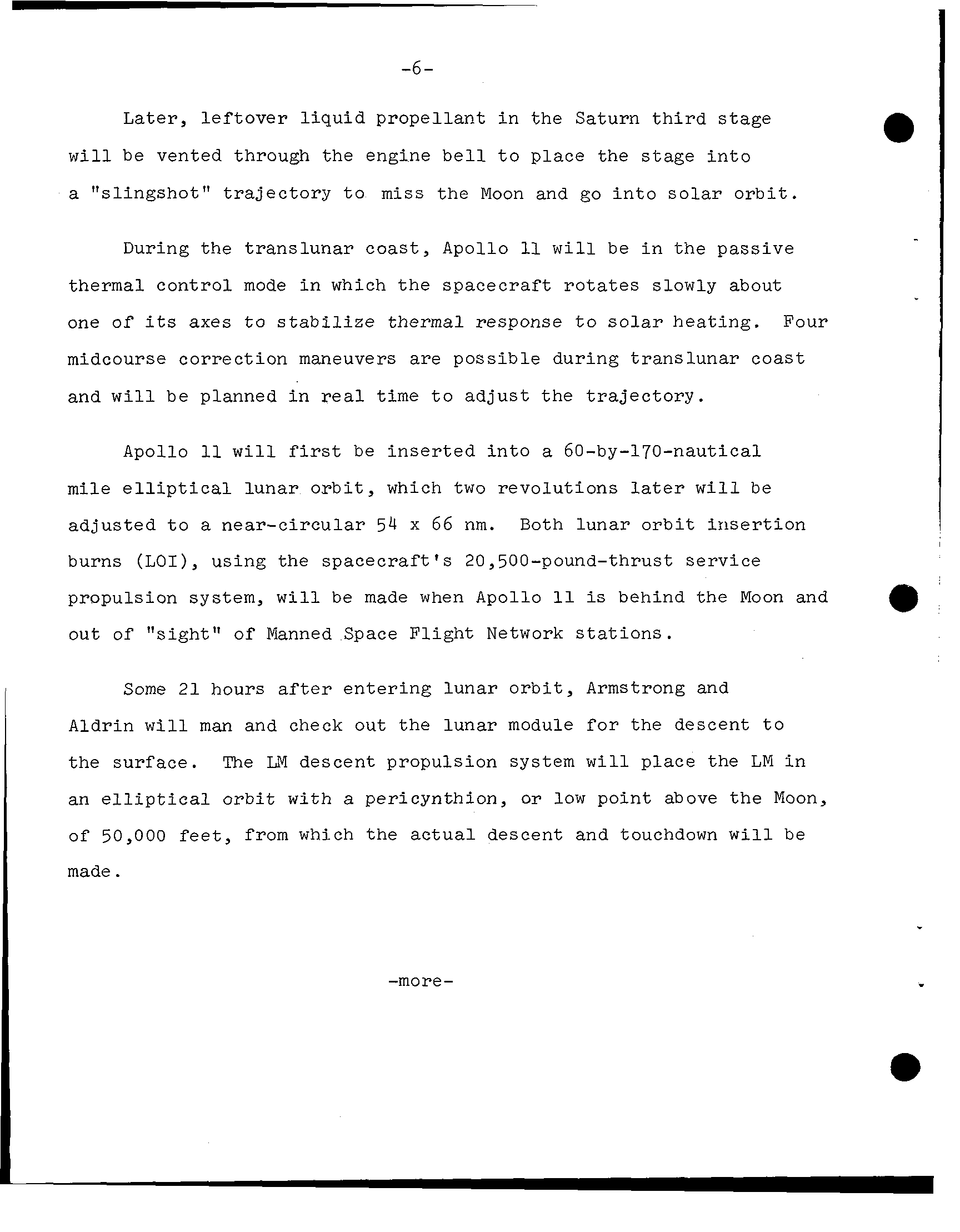
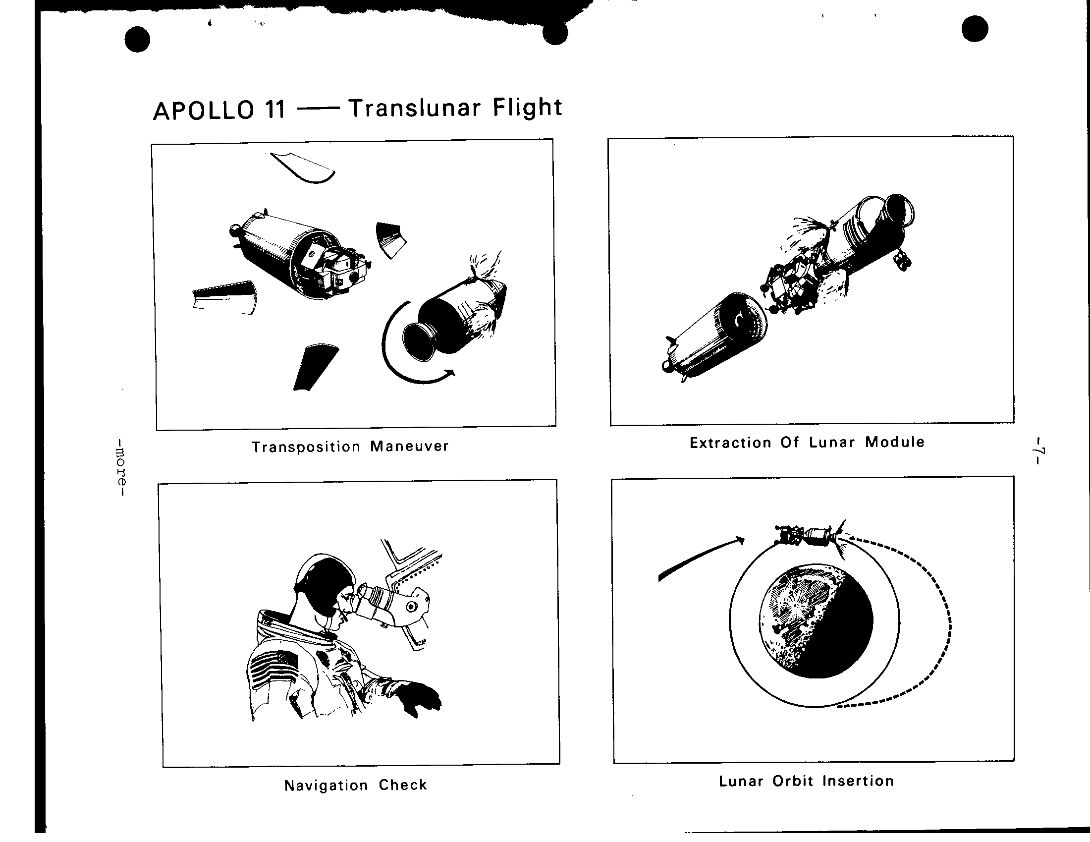
-6 l e f t o v e r l i q u i d propellant i n the Saturn t h i r d stage w i l l vented through the engine b e l l t o place the stage i n t o "slingshot" t r a j e c t o r y t o m i s s the Moon and go i n t o s o l a r o r b i t. During the translunar coast, Apollo w i l l be i n the passive control mode i n which t h e spacecraft r o t a t e s slowly about one of axes t o s t a b i l i z e response t o s o l a r heating. Four midcourse correction maneuvers are possible during translunar coast and w i l l be planned i n t i m e to adjust t h e t r a j e c t o r y. Apollo w i l l be i n s e r t e d i n t o a 60-by-170-nautical m i l e e l l i p t i c a l lunar o r b i t, which two revolutions w i l l be adjusted t o near-circular 54 x 66 nm. Both lunar o r b i t i n s e r t i o n burns (L O I), using the spacecraft's 20,500-pound-thrust service a propulsion s y s t e m, w i l l made when Apollo behind the Moon and out of of Manned Space Flight Network s t a t i o n s. Some 2 1 hours entering lunar o r b i t, Armstrong and Aldrin w i l l man and check out the lunar module f o r the descent t o surface. LM descent propulsion system w i l l place the LM i n an e l l i p t i c a l o r b i t w i t h pericynthion, or low point above the Moon, of 50,000 f e e t, from which the a c t u a l descent and touchdown w i l l made. -more-
APOLLO 11 Translunar Flight Extraction Of Lunar Mo d u le Transposition Maneuver Lunar Orbit Insertion Navigation Check
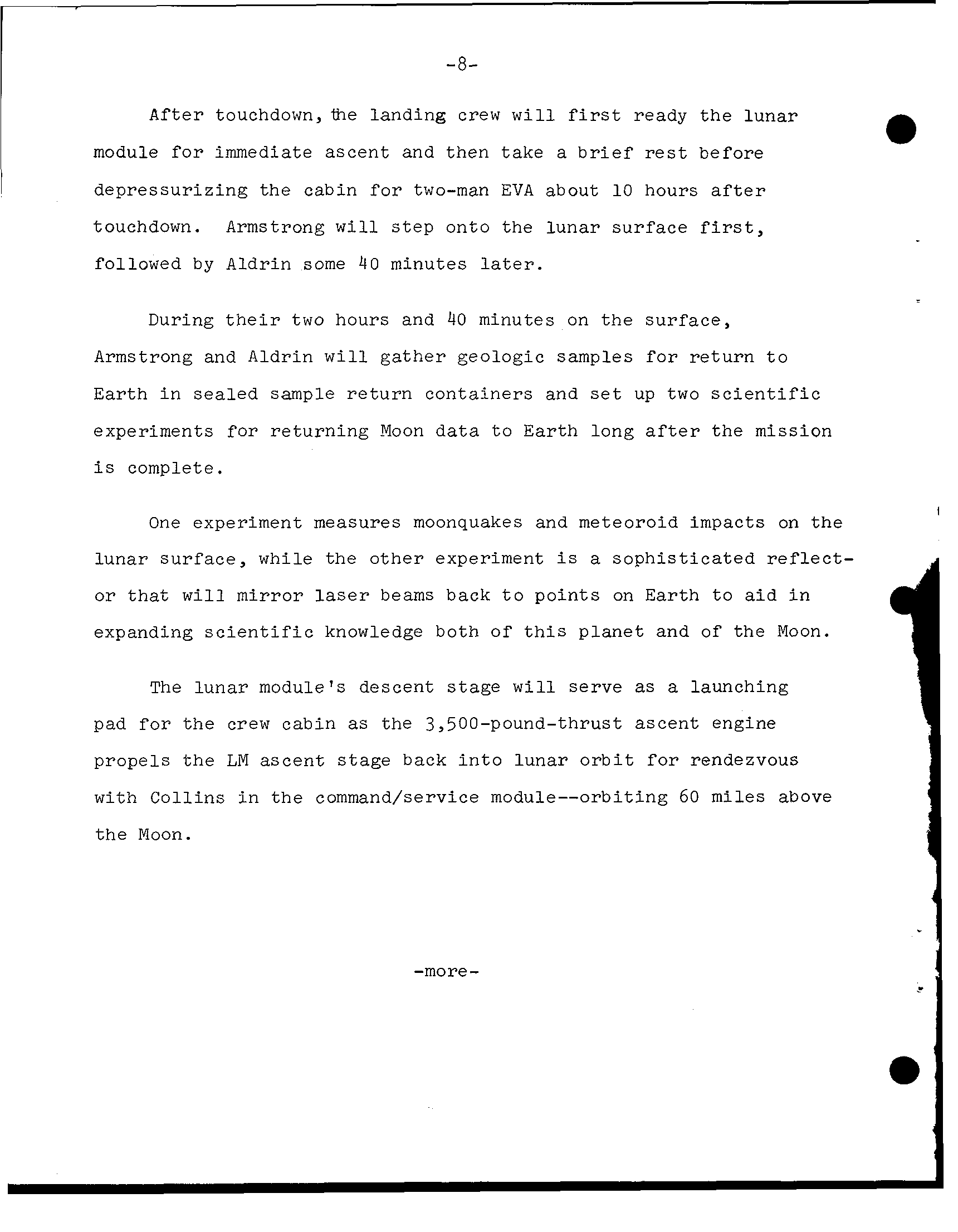
-8- After touchdown,ihe landing crew w i l l ready t h e lunar module for immediate ascent and then take a before depressurizing the cabin for two-man EVA about 10 hours a f t e r touchdown. Armstrong w i l l s t e p onto the lunar surface followed by Aldrin some 4 0 minutes l a t e r. During t h e i r two hours and 40 minutes on t h e surface, Armstrong and Aldrin w i l l gather geologic samples for return t o E a r t h i n sample return containers and up two s c i e n t i f i c experiments for returning Moon t o Earth long a f t e r the mission complete. One experiment measures moonquakes and meteoroid impacts on the lunar surface, while the other experiment sophisticated r e f l e c t - or that w i l l mirror beams back t o points on E a r t h t o a i d i n expanding s c i e n t i f i c knowledge both of t h i s planet and of the Moon. The lunar module's descent stage w i l l serve launching pad f o r t h e crew cabin the 3,500-pound-thrust ascent engine propels the LM ascent back i n t o lunar o r b i t for rendezvous w i t h Collins i n t h e command/service module--orbiting 60 miles above t h e Moon. -more-
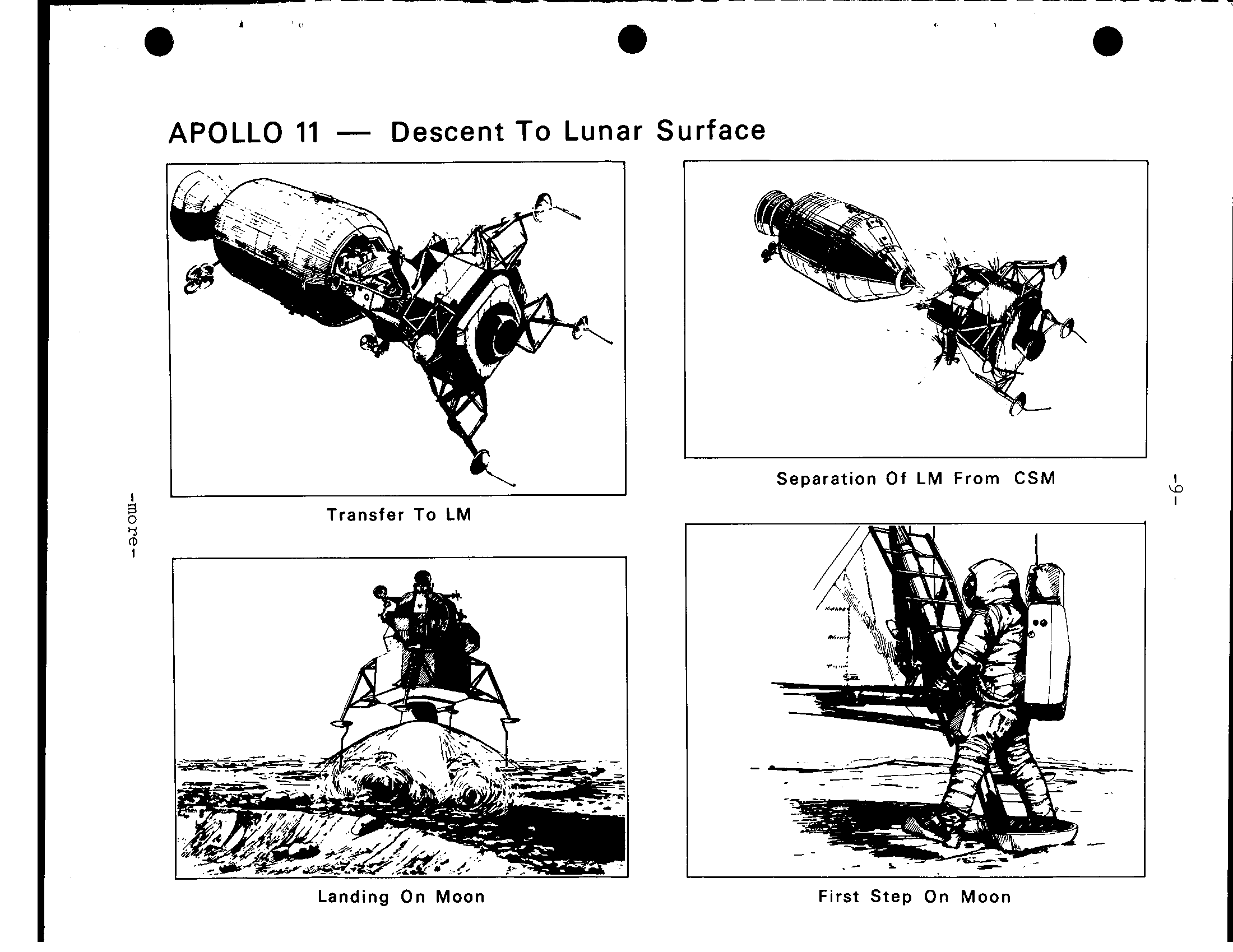
APOLLO 11 Descent To Lunar Surface Separation Of L M From CSM I I Transfer To LM 1 I . - .. Landing On Moon First Step On Moon
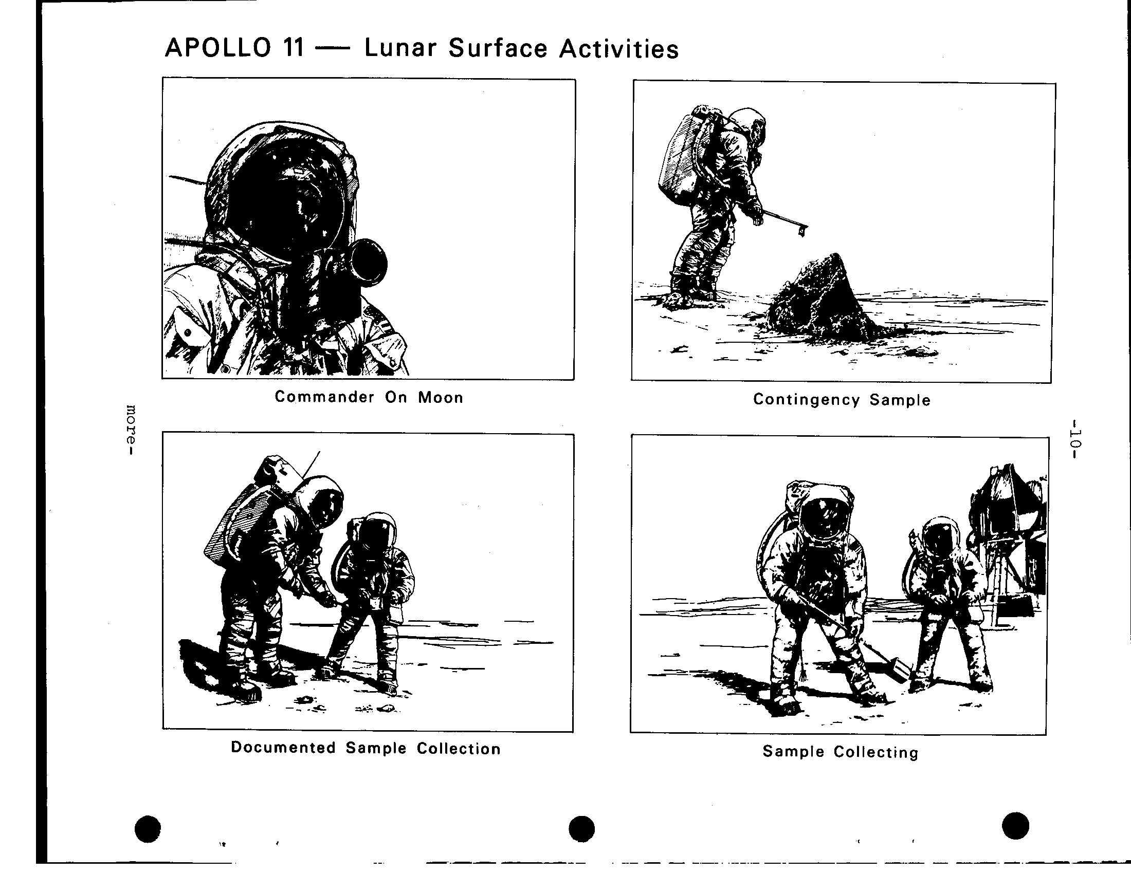
APOLLO 11 Lunar Surface Activities Commander On Moon Contingency Sample Documented Sample Collection Sample Collecting
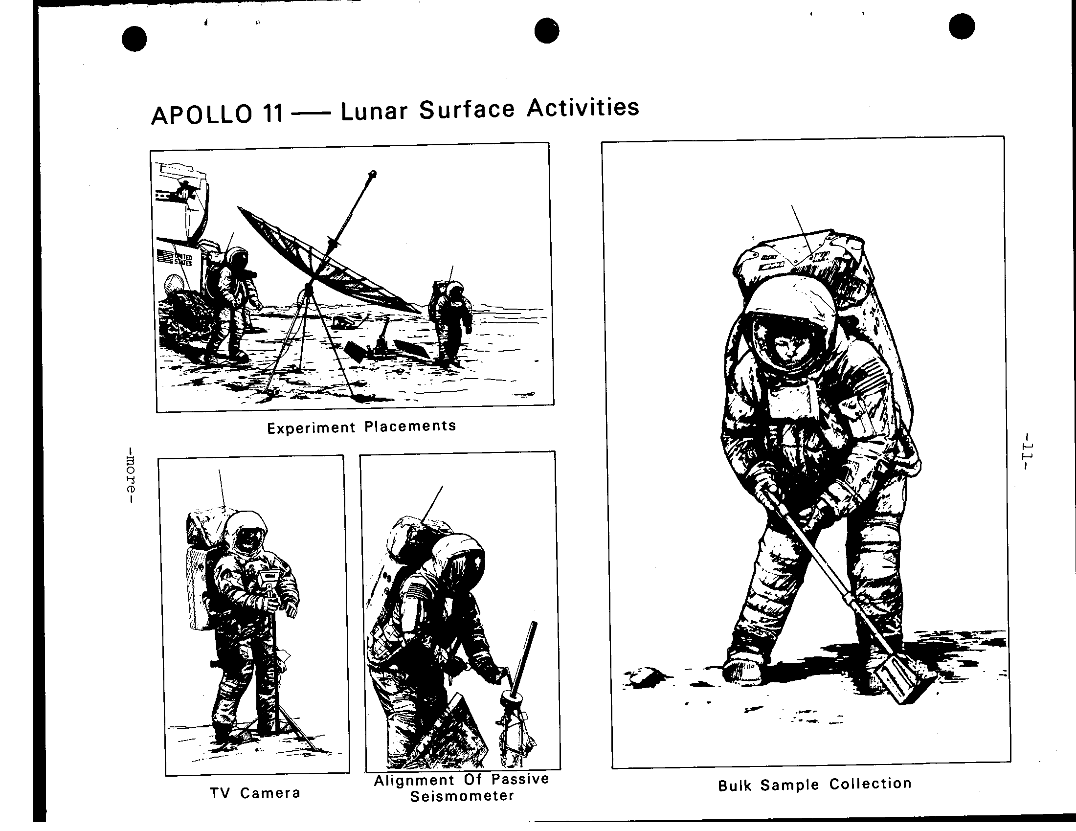
e ties APOLLO 11 Lunar Surface Activ - P Experiment Placements __ . - Bulk Sample Collection TV Camera Seismometer
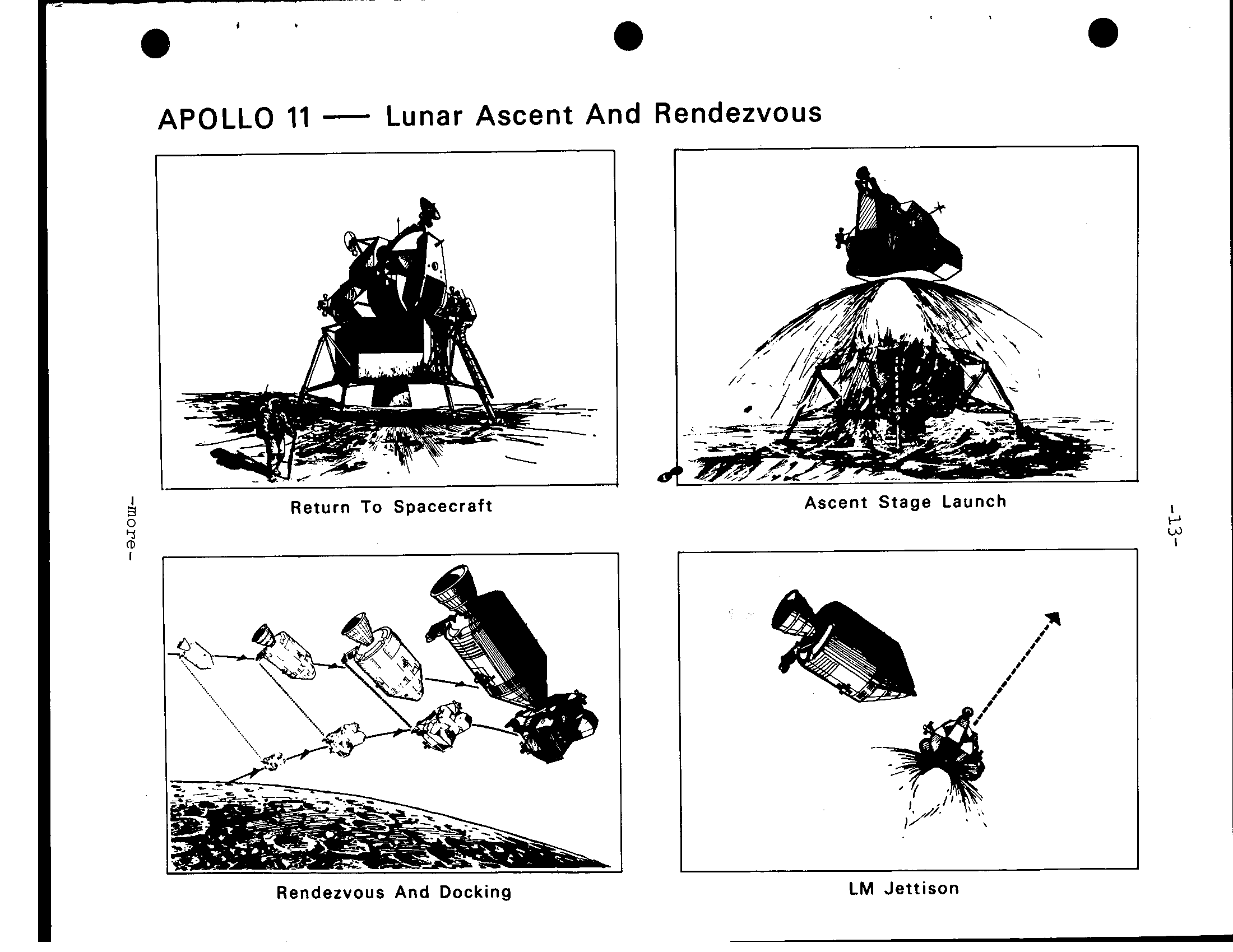
-12- Four basic maneuvers, performed by LM crew using t h e spacecraft's small maneuvering and a t t i t u d e t h r u s t e r s, w i l l bring the LM and t h e command module together f o r docking about three and h a l f hours a f t e r l i f t o f f from the Moon. The boost out of lunar o r b i t for t h e r e t u r n journey planned for about 135 hours after E a r t h l i f t o f f and LM ascent stage been jettisoned and lunar samples and f i l m stowed aboard the command module. An optional plan provides f o r 12-hour delay i n t h e transearth i n j e c t i o n burn t o allow t h e crew more long hard day's work on lunar surface and f l y i n g the rendezvous. t o t a l mission t i m e t o splashdown would remain about since t h e transearth i n j e c t i o n burn would impart higher velocity to bring t h e spacecraft back to t h e mid-Pacific recovery l i n e about same t i m e. rendezvous sequence t o be flown on Apollo twice been flown w i t h the Apollo spacecraft---once i n E a r t h o r b i t on Apollo 9 and once i n lunar o r b i t w i t h Apollo 1 0. The Apollo 10 mission duplicated, except f o r a c t u a l landing, aspects of t h e Apollo timeline. -more- -
a e I APOLLO 11 Lunar Ascent And Rendezvous Ascent Stage Launch Return To Spacecraft LM Jettison Rendezvous And Docking
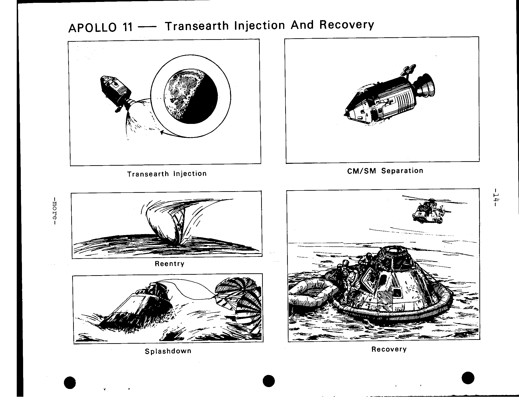
APOLLO 11 Transearth Injection And Recovery CM/SM Separation Transearth injection I 2 Reentry Recovery Splashdown . .
-15- During t h e t r a n s e a r t h c o a s t p e r i o d, Apollo w i l l again c o n t r o l s o l a r h e a t loads by u s i n g t h e passive thermal c o n t r o l "barbeque" technique. Three t r a n s e a r t h midcourse c o r r e c t i o n s are p o s s i b l e and w i l l be planned i n real time t o a d j u s t t h e E a r t h e n t r y c o r r i d o r. Apollo w i l l e n t e r t h e E a r t h's atmosphere (400,000 195 hours f i v e minutes after launch 36,194 p e r second. Command module touchdown w i l l be 1285 n a u t i c a l m i l e s downrange from e n t r y 10.6 degrees n o r t h l a t i t u d e by 1 7 2. 4 west longitude 195 hours, 19 minutes E a r t h launch 1 2: 4 6 p.m. EDT J u l y 2 4. The touchdown p o i n t about 1040 n a u t i c a l miles southwest of Honolulu, H a w a i i. (END OF GENERAL RELEASE; BACKGROUND INFORMATION FOLLOWS) -more-
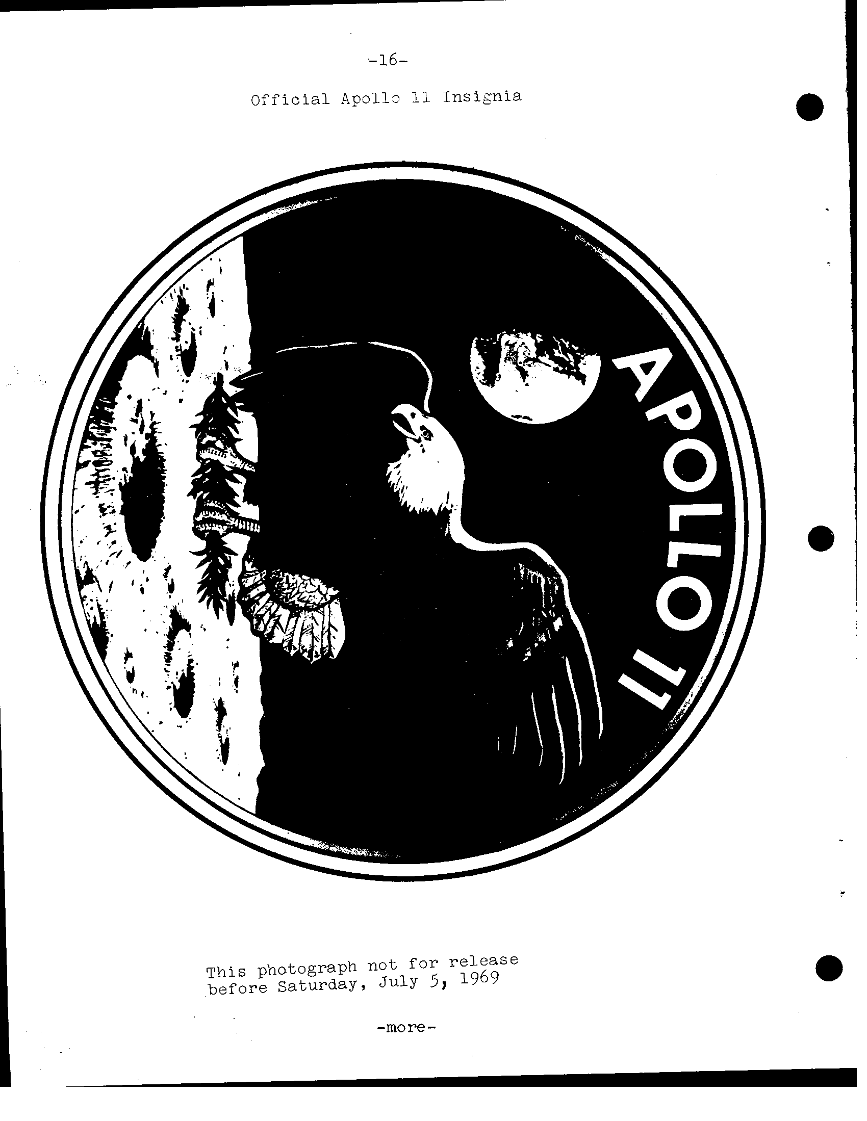
-16- Official Apollo 11 Insisnia This photograph not f o r release 5, 1969 before Saturday, July -more-
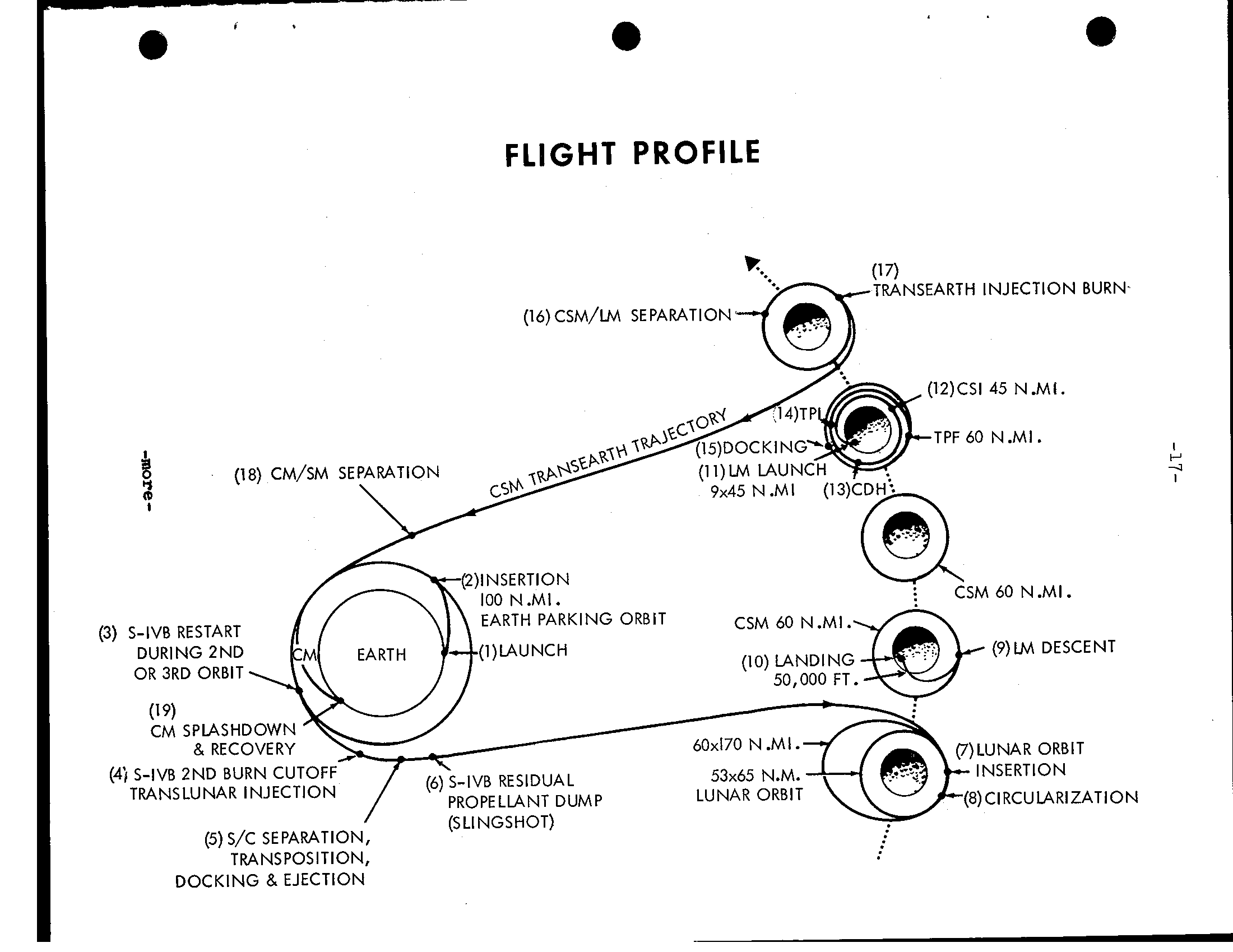
e FLIGHT PROFILE (12)CSI 45 . TPF 60 (18) CM/St SEPARATION EARTH PARKING ORBIT CSM 60 N (3) DURING 2ND OR 3RD ORBIT (19) CM SPLASHDOWN (4) S-IVB 2ND BURN CUTOFF TRANSLUNAR INJECTION PROPELLANT DUMP (8) CIRCULARIZATION (5) S /C SEPARATION, TRANSPOSITION, DOCKING 8. EJECTION
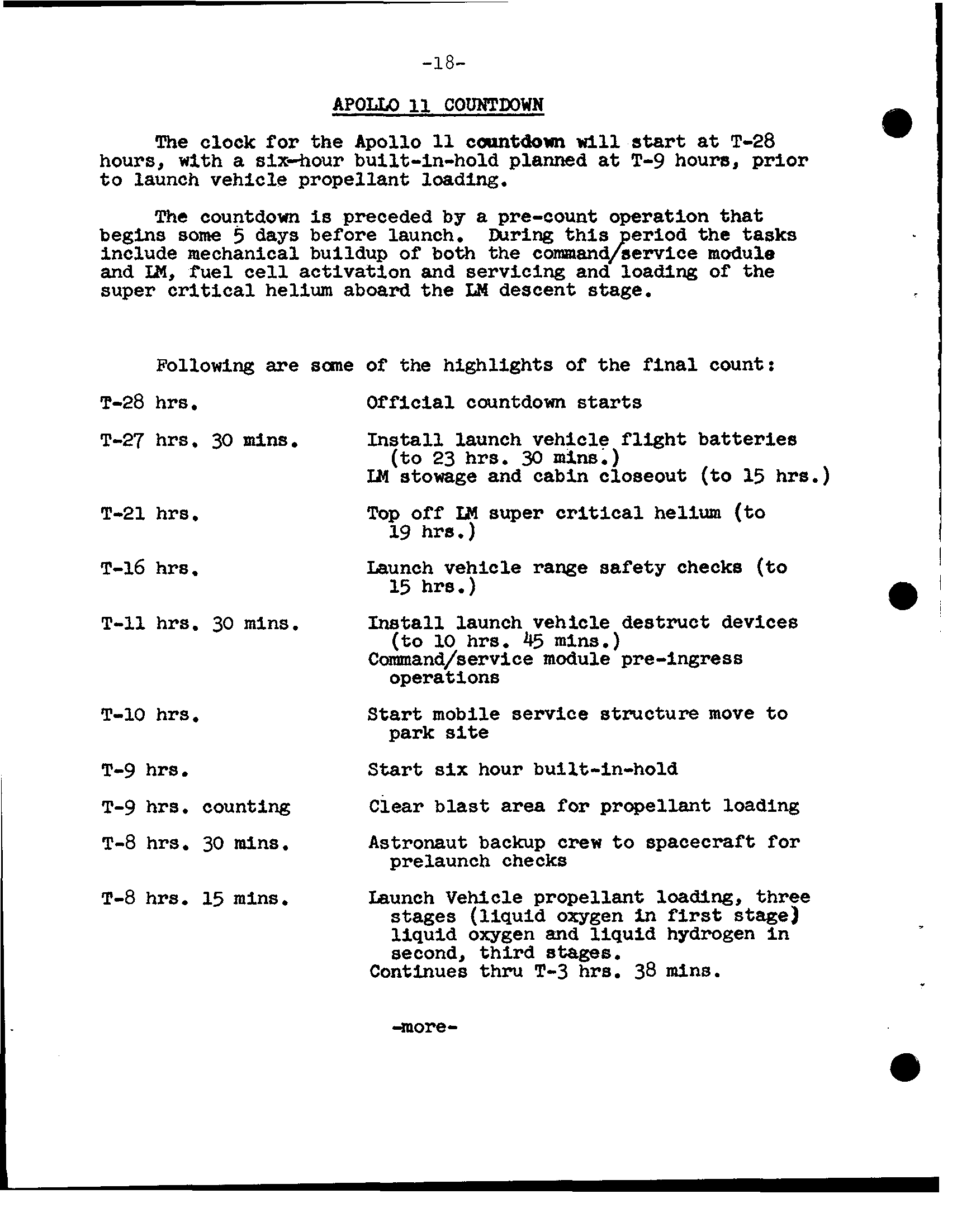
-18- A P O W COUNTDOWN clock for the Apollo camtdown T-28 hours, with six-hour built-in-hold planned T-9 houra, prior t o launch vehicle propellant countdown preceded by pre-count operation that begins some 5 days before launch. During t h i s eriod include mechanical buildup of both the cornandjellrice module IM, f u e l activation and servicing and loading of super critical aboard the LF4 descent Following of highlights of the final count: countdown T-28 hrs T-27 hrs, 30 mins. Install launch vehicle batteries (to 23 hrs. 30 mins.) and cabin closeout (to 15 hrs.) T-21 hrs. Top off IM helium (to 19 h r E.) T-16 Launch vehicle checks (to 15 hrs. ) h rs . 30 mins. Inatall launch vehicle destruct devices (to 45 m i n s.) Command/service module operations T-10 hrs. mobile service structure move t o T-9 hrs. six hour built-in-hold T-9 hrs. counting for propellant loading T-8 hrs. 30 mins. Astronaut backup crew t o spacecraft for prelaunch checks T-8 mins. Launch VeNcle propellant loading, (liquid oxygen in liquid oxygen and liquid hydrogen i n second, stages. Continues thru T-3 hrs. 38 mlnrr. -more-
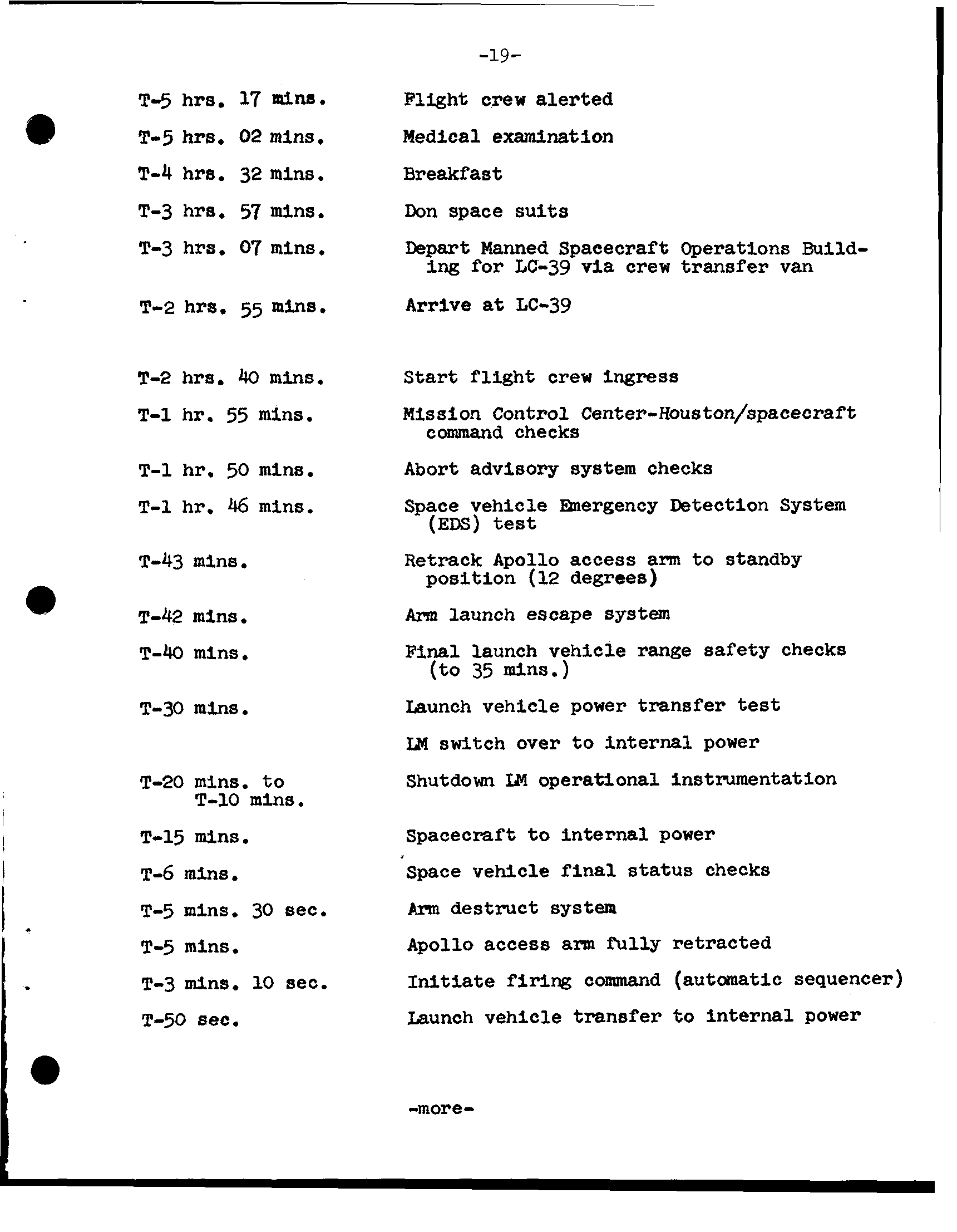
-19- T-5 hrs. 17 Flight crew alerted . T-5 hrs. 02 mins Medical examination T-4 hrs. 32 m i n s. T-3 hrs. 57 mins. Don space suits T-3 hrs. Q7 mins. Manned Spacecraft Operations Build- ing for LC-39 via crew van Arrive LC-39 T-2 hrs. 55 mins. T-2 hra. 40 mins. crew 55 mins. Mission Control Center-Houston/spacecraft command checks 50 mins. Abort advisory system checks 46 mins. vehicle mergency Detection T-43 mins. Retrack Apollo access arm t o standby position a T-42 mins. Arm launch system T-40 mins, F i n a l launch vehicle range checks (to 35 mins. 1 Launch vehicle power transfer test T-30 m l n s. IN over t o internal power T-20 mins. t o Shutdown XN operational instrumentation T-10 mins. T-15 mins. Spacecraft t o internal power I I T-6 mins. Space vehicle f i n a l status checks I. T-5 mins. 30 sec. A ~ I U destruct system T-5 mins. Apollo access fully retracted firing command (automatic sequencer) T-3 mins. 10 sec. Launch vehicle transfer t o internal power T-50 8ec. I. -more-
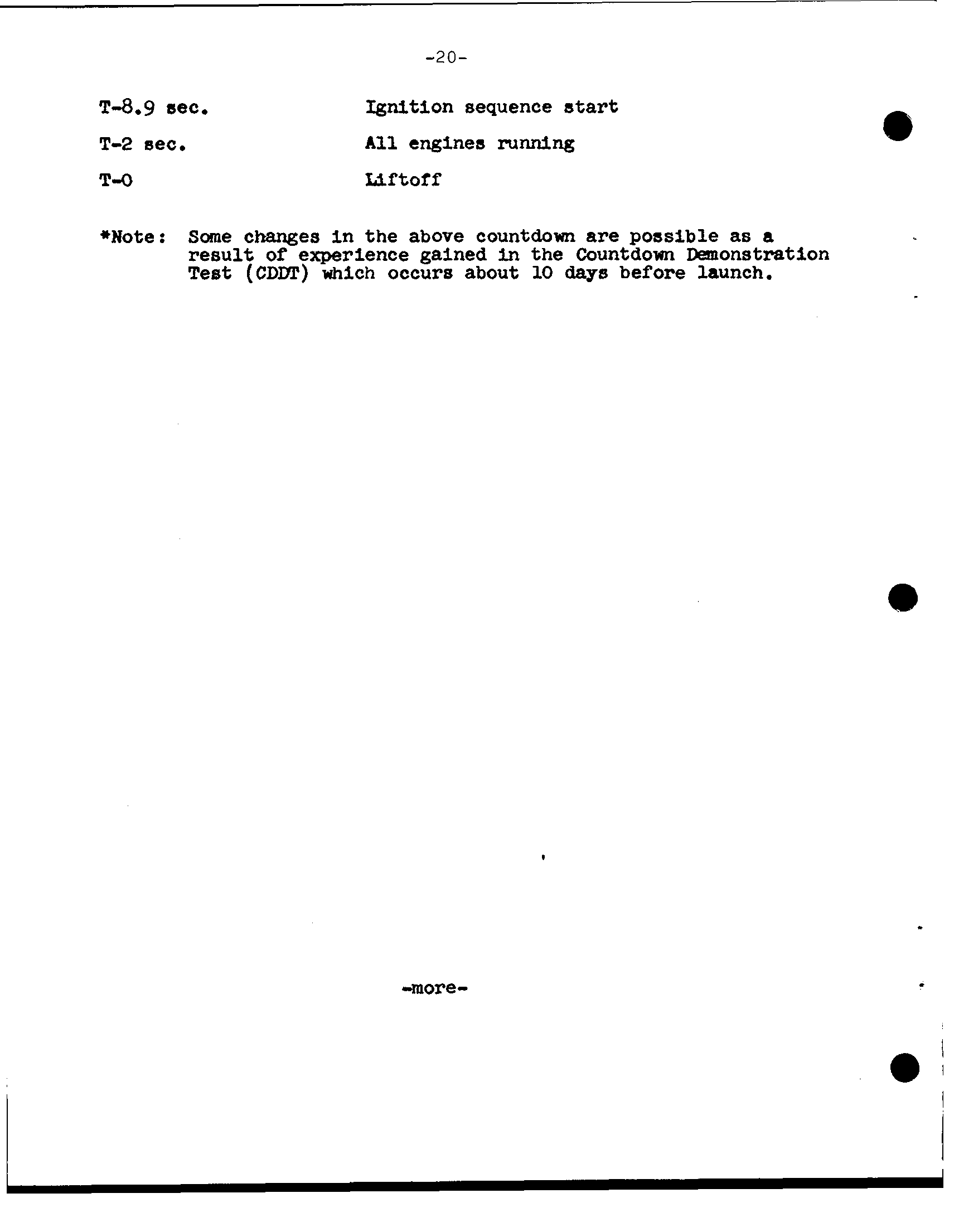
-20- T-8.9 sec. Ignition sequence start T-2 A l l engines running T-O Liftoff Some in the above countdown are possible a result of experience gained i n the Countdown Dmonstratlon Test (CDDT) which occurs about days launch. -more-
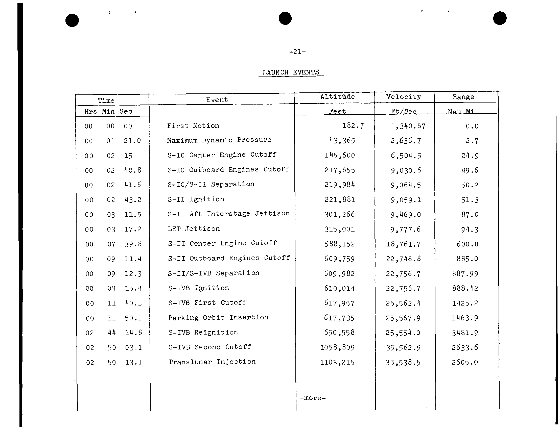
-21- LAUNCH EVENTS Altithde Velocity Range Time Event Min See Feet Ft/Ser. 182.7 1,340.67 00 00 00 F i r s t Motion 0.0 00 01 21.0 Maximum Dynamic Pressure 43,365 2,636.7 2.7 145,600 24.9 00 02 15 S-IC Center Engine Cutoff 6,504.5 00 02 40.8 S-IC Outboard Engines Cutoff 217,655 9,030.6 49.6 00 02 41.6 s-IC/S-II Separation 219,984 9,064.5 50.2 00 02 43.2 S-I1 Ignition 221,881 9,059.1 51.3 301,266 87.0 00 03 11.5 S-I1 A f t Interstage J e t t i s o n 9,469.0 00 03 17.2 LET J e t t i s o n 315,001 9,777.6 94.3 00 07 39.8 S-I1 Center Engine Cutoff 588,152 18,761.7 600.0 a 00 09 11.4 S-I1 Outboard Engines Cutoff 609,759 22,746. 885.0 00 09 12.3 S-II/S-IVB Separation 609,982 22,756.7 887.99 09 15.4 S-IVB Ignition 610,014 22,756.7 888.42 00 11 40.1 S-IVB F i r s t Cutoff 617,957 25,562.4 1425.2 00 11 50.1 Parking O r b i t Insertion 617,735 25,567.9 1463.9 44 14.8 S-IVB Reignition 650,558 25,554 3481.9 02 .O 02 50 03.1 S-IVB Second Cutoff 105a,809 35,562.9 2633.6 02 50 13.1 Translunar Injection 1103,215 35,538.5 2605.0 -more-
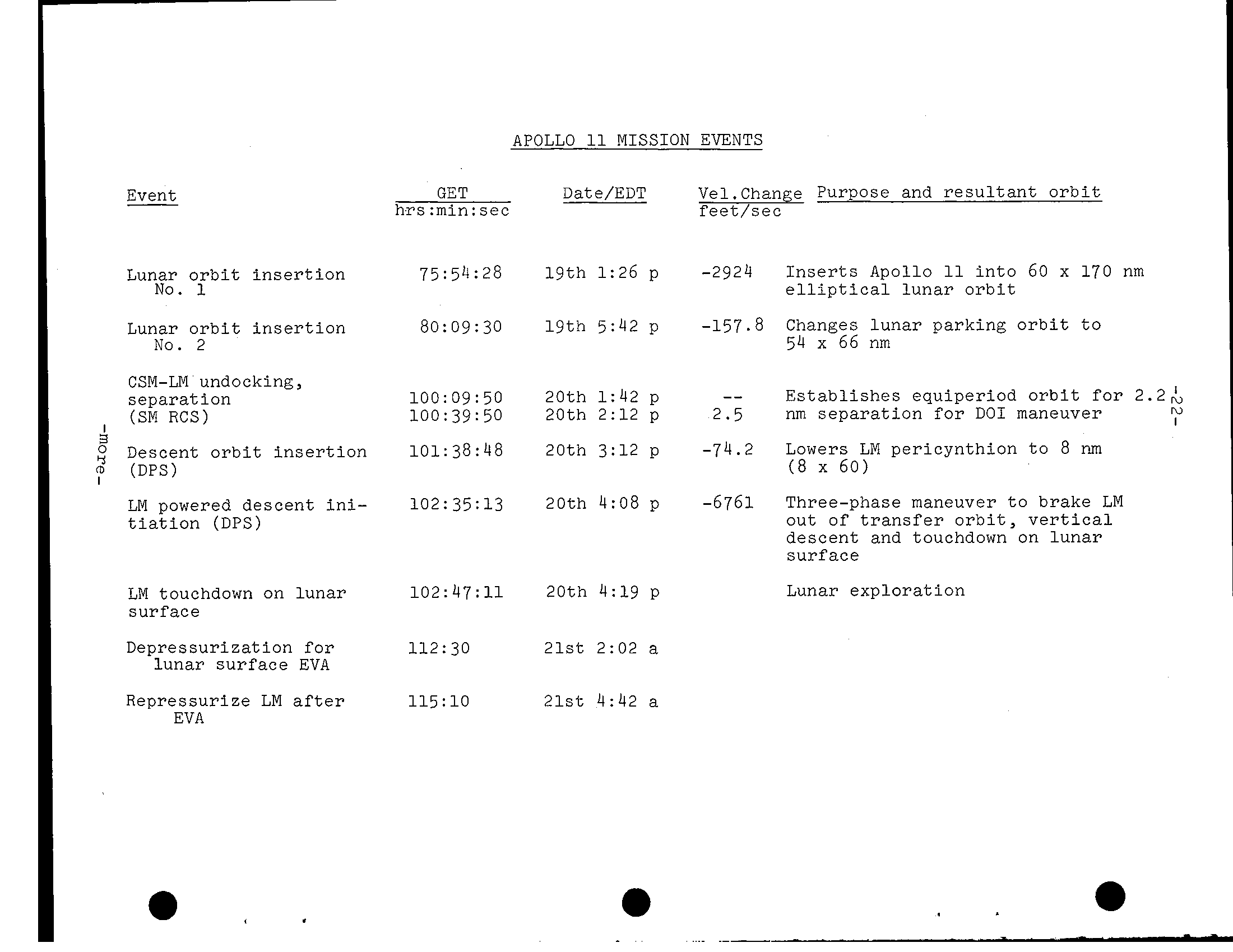
APOLLO 11 MISSION EVENTS GET Date/EDT Vel.Change Purpose and resultant orbit Event hrs:min:s ee feet/sec Inserts Apollo 11 into 60 x 170 nm Lunar orbit insertion 75:54:28 19th 1:26 p -2924 No. 1 elliptical lunar orbit -157.8 Changes lunar parking orbit to Lunar orbit insertion 80:0 9:3 0 19th 5:42 p 54 x 66 nm No. 2 CSM-LM undocking, -- 20th 1:42 p Establishes equiperiod orbit for 2.2& separation 100: 0 9 50 nm separation for DO1 maneuver (SM RCS) 100:39:5 0 20th 2:lZ p 2.5 i 5 20th 3:lZ p -74.2 Lowers LM pericynthion to 8 nm Descent orbit insertion 101: 3 8:48 (8 x 60) (DPS) 20th 4:08 p -6761 Three-phase maneuver to brake LM LM powered descent ini- 102: 35:13 out of transfer orbit, vertical tiation (DPS) descent and touchdown on lunar surface 47: 4:19 p Lunar exploration LM touchdown on lunar 102: 2 0 t h surfa ce Depressurization for 112:30 2lst 2:02 a lunar surface EVA Repressurize LM after 115 10 21st 4:42 a EVA
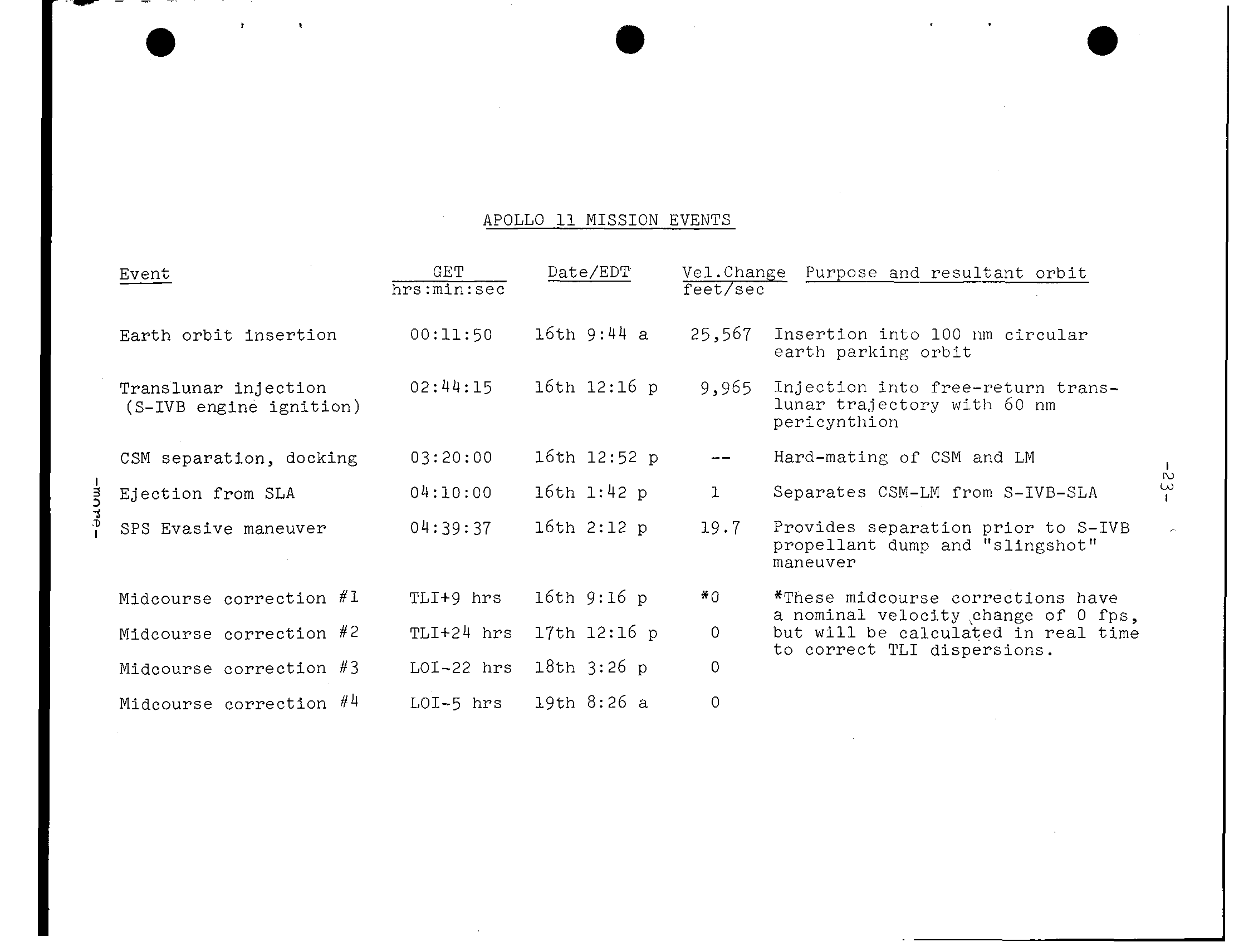
a APOLLO MISSION EVENTS Event GET Date/EDT Vel.Chan e Purpose and r e s u l t a n t o r b i t hrs:min:sec E a r t h o r b i t i n s e r t i o n 00:11:50 1 6 t h 9: 4 4 25,567 I n s e r t i o n i n t o 1 0 0 iiin c i r c u l a r p a r k i n g o r b i t T r a n s l u n a r i n j e c t i o n 02:44: 15 1 6 t h 1 2: 1 6 p 9,965 I n j e c t i o n i n t o f r e e - r e t u r n t r a n s - (S-IVB engine i g n i t i o n) l u n a r t r a j e c t o r y with 6 0 nm pericyntliion CSM s e p a r a t i o n, docking 03:20:00 1 6 t h 1 2: 5 2 p Hard-mating of CSM and LM I 3 E j e c t i o n from SLA 04:10:00 1 6 t h 1:42 p 1 S e p a r a t e s CSM-LM from S-IVB-SLA 3 :. SPS Evasive maneuver 04:39: 37 1 6 t h 2:12 p 19.7 Provides s e p a r a t i o n p r i o r t o S-IVB p r o p e l l a n t dump and “s l i n g s h o t” maneuver Midcourse c o r r e c t i o n #‘I TLI+g h r s 1 6 t h 9:16 p * O *These midcourse c o r r e c t i o n s have a nominal v e l o c i t y <change of 0 f p s, Midcourse c o r r e c t i o n f#2 TLI+24 h r s 1 7 t h 1 2: 1 6 p 0 b u t w i l l c a l c u l a t e d i n time t o c o r r e c t T L I d i s p e r s i o n s. Midcourse c o r r e c t i o n #3 LOI-22 18th 3:26 p 0 Midcourse c o r r e c t i o n # 4 LOI-5 1 9 t h 8:26 0
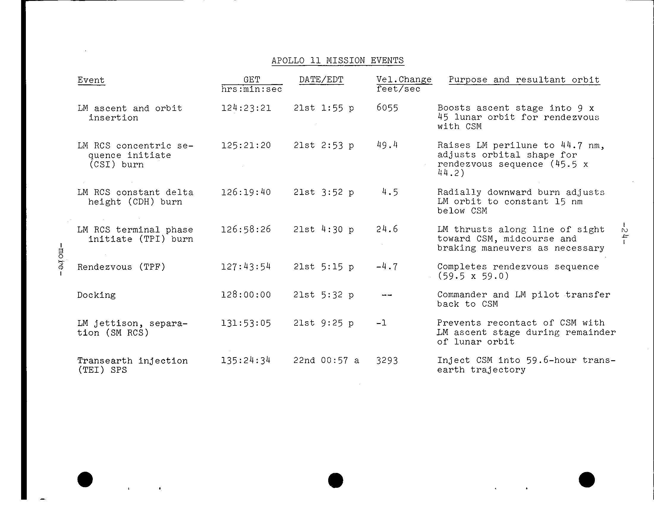
APOLLO MISSION EVENTS Event GET DATE/EDT Vel.Change Purpose and r e s u l t a n t o r b i t hrs :'min: s e c LM a s c e n t and o r b i t 1 2 4 :23 : 2 1 2 l s t 1:55 p 6055 Boosts a s c e n t i n t o 9 x i n s e r t i o n 45 l u n a r o r b i t for rendezvous w i t h CSM LM RCS c o n c e n t r i c se- 125:21: 20 21st 2:53 P 4 9. 4 LM p e r i l u n e t o 44.7 nm, quence i n i t i a t e a d j u s t s o r b i t a l shape for (CSI) burn rendezvous sequence (45.5 x 44.2) LM RCS c o n s t a n t d e l t a 126:19:40 2 1 s t 3:52 p 4.5 R a d i a l l y downward burn a d j u s t s height (C D H) burn LM o r b i t t o c o n s t a n t 15 nm below CSM LM RCS t e r m i n a l phase 126:58:26 2 l s t 4:30 p 24.6 LM t h r u s t s a l o n g l i n e o f s i g h t i n i t i a t e (T P I) burn toward CSM, midcourse and B braking maneuvers as necessary m Rendezvous (TPF) 127:43: 54 2 l s t 5:15 p -4.7 Completes rendezvous sequence I (59.5 x 59.0) -- Docking 128:OO:OO 21st 5:32 p Commander and LM p i l o t t r a n s f e r back t o CSM LM j e t t i s o n, separa- 131: 53: 05 9:25 p P r e v e n t s r e c o n t a c t of CSM w i t h t i o n (SM RCS) LM a s c e n t stage d u r i n g remainder of l u n a r o r b i t T r a n s e a r t h i n j e c t i o n 135:24:34 22nd 00:57 a 3293 I n j e c t CSM i n t o 59.6-hour t r a n s - (TEI) SPS t r a j e c t o r y
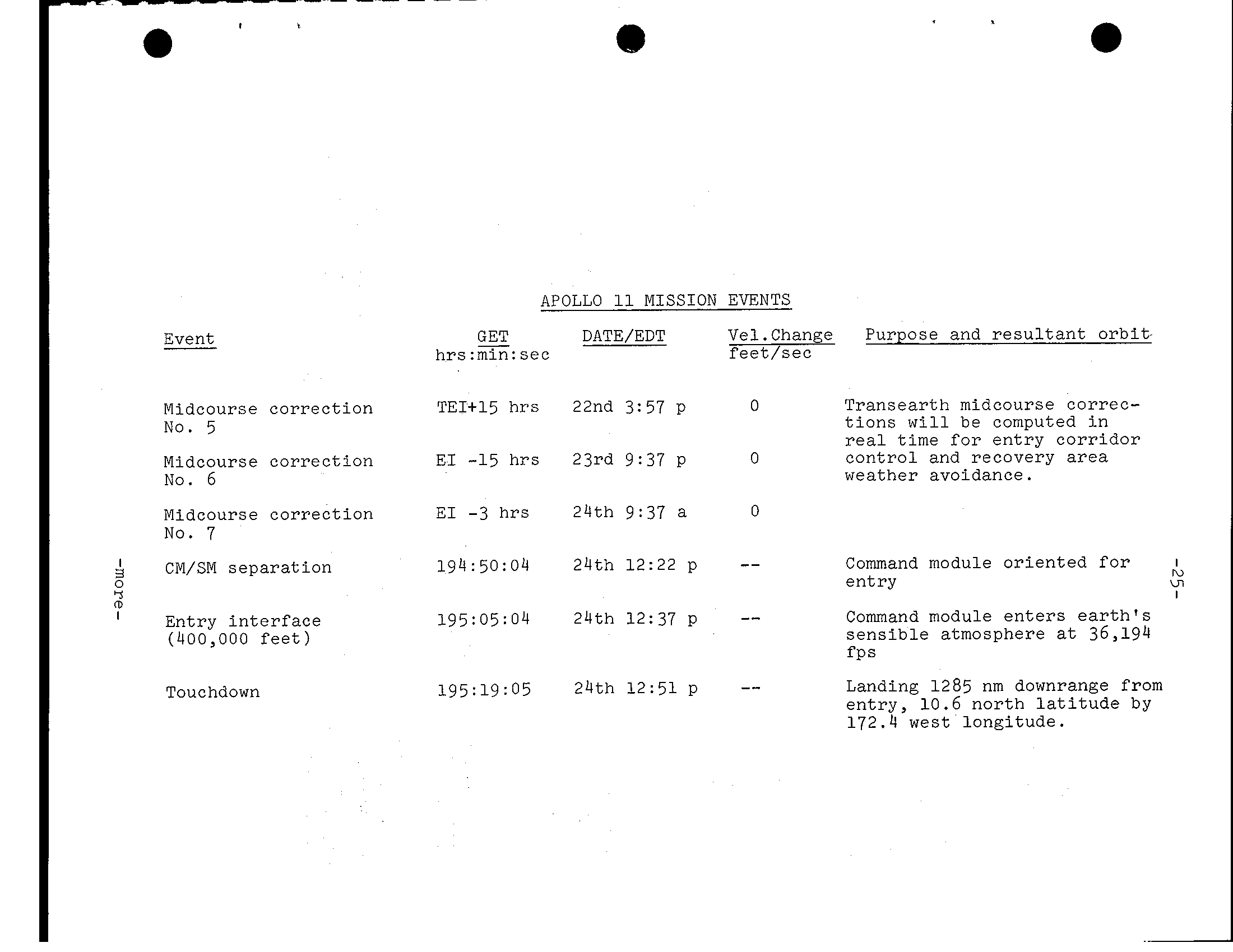
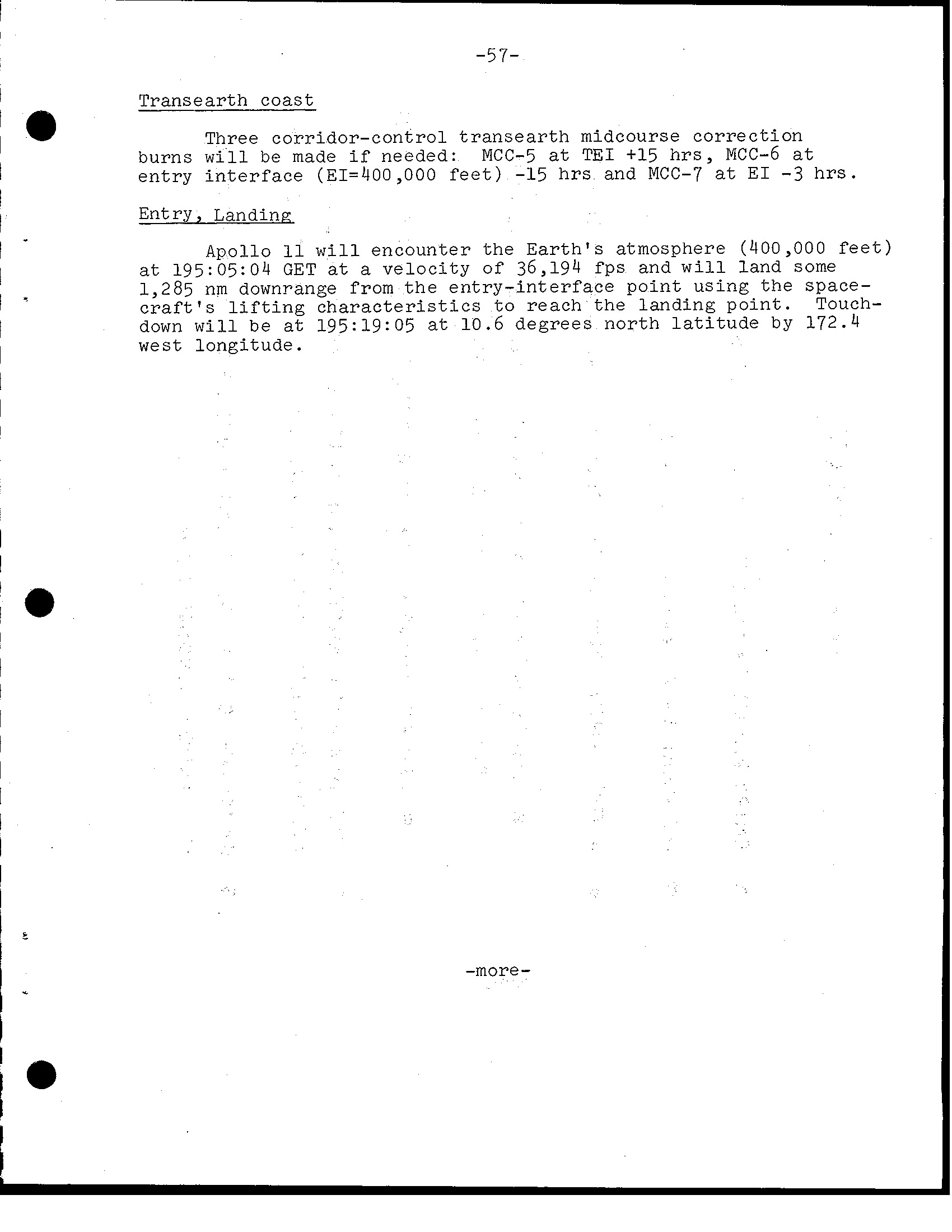
APOLLO 11 MISSION EVENTS GET DATE/EDT Vel.Change Purpose and resultant orbit- Event hrs:min:sec feet/sec Transearth midcourse correc- Midcourse correction TEI+15 hrs 22nd 3:57 P tions will be computed in No. 5 real time for entry corridor control and recovery area Midcourse correction EI -15 hrs 23rd 9:37 P weather avoidance. No. 6 -3 24th 9:37 a Midcourse correction EI h r s No. 7 4 Command module oriented for CM/SM separation 194 50: 04 24th 12:22 p ru entry u- m Command module enters earth's Entry interface 195:05:04 24th 12:37 p sensible atmosphere at 36,194 (400,000 feet) fP s Landing 1285 nm downrange from Touchdown entry, 10.6 north latitude by 172.4 west longitude.
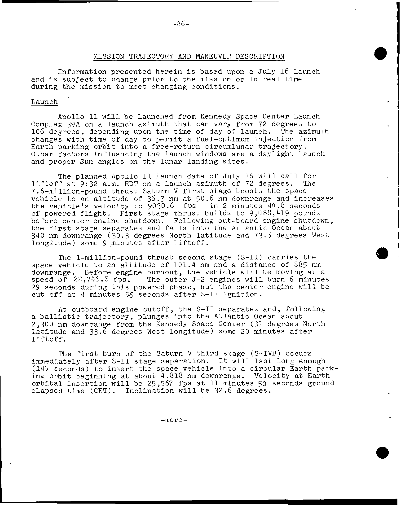
-26- MISSION TRAJECTORY AND MANEUVER DESCRIPTION Information presented herein based upon July 16 launch and subject t o change p r i o r t o t h e mission o r i n r e a l time during t h e mission t o meet changing conditions. Launch Apollo w i l l be launched from Kennedy Space Center Launch Complex 39A on launch azimuth t h a t can vary from 72 degrees t o 106 degrees, depending upon the time of day of launch. The azimuth changes with time of day t o permit fuel-optimum i n j e c t i o n from E a r t h parking o r b i t i n t o free-return circumlunar t r a j e c t o r y. Other f a c t o r s influencing the launch windows a r e daylight launch and proper Sun angles on the lunar landing The planned Apollo launch date of J u l y 1 6 w i l l c a l l f o r l i f t o f f 9:32 a. m. EDT on launch azimuth of 72 degrees. The 7.6-million-pound t h r u s t Saturn V boosts t h e space vehicle t o an a l t i t u d e of 36.3 nm 50.6 nm downrange and increases t h e v e h i c l e's velocity t o 9030.6 fps i n 2 minutes 4'3.8 seconds of powered f l i g h t. F i r s t stage t h r u s t builds t o 9,088,419 pounds before center engine shutdown. Following out-board engine shutdown, the stage separates and i n t o the A t l a n t i c Ocean about 340 nm downrange (30.3 degrees North l a t i t u d e and 73.5 degrees West longitude) some 9 minutes a f t e r l i f t o f f. 1-million-pound t h r u s t second stage (S-11) c a r r i e s the space vehicle t o an a l t i t u d e of 1 0 1. 4 nm and distance of 885 nm downrange. Before engine burnout, the vehicle w i l l be moving speed of 22,746.8 fps. The o u t e r J-2 engines w i l l burn 6 minutes 29 seconds during t h i s powered phase, but t h e center engine w i l l be cut off 4 minutes 56 seconds a f t e r S-I1 i g n i t i o n. A t outboard engine c u t o f f, t h e S-I1 separates and, following b a l l i s t i c t r a j e c t o r y, plunges i n t o t h e Atlantic Ocean about 2,300 nm downrange from t h e Kennedy Space Center (3 1 degrees North l a t i t u d e and 33.6 degrees West longitude) some 2 0 minutes a f t e r l i f t o f f. The burn of t h e Saturn V t h i r d stage (S-IVB) occurs immediately a f t e r S-I1 stage separation. w i l l l a s t long enough (145 Seconds) t o i n s e r t t h e space vehicle i n t o c i r c u l a r Earth park- i n g O r b i t beginning about 4,818 nm downrange. Velocity Earth o r b i t a l i n s e r t i o n w i l l be 25,567 f p s minutes 50 seconds ground elapsed time (GET). I n c l i n a t i o n w i l l be 32.6 degrees. .. -more-
I . I
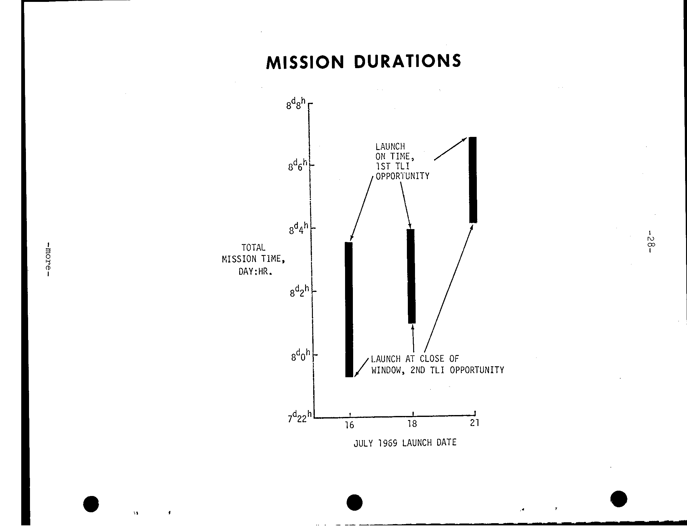
MISSION DURATIONS gdqh I TOTAL NISSION TlME, DAY:HR. 8d2h gdOh , I 7d221. 16 18 21 JULY 1969 LAUNCH DATE
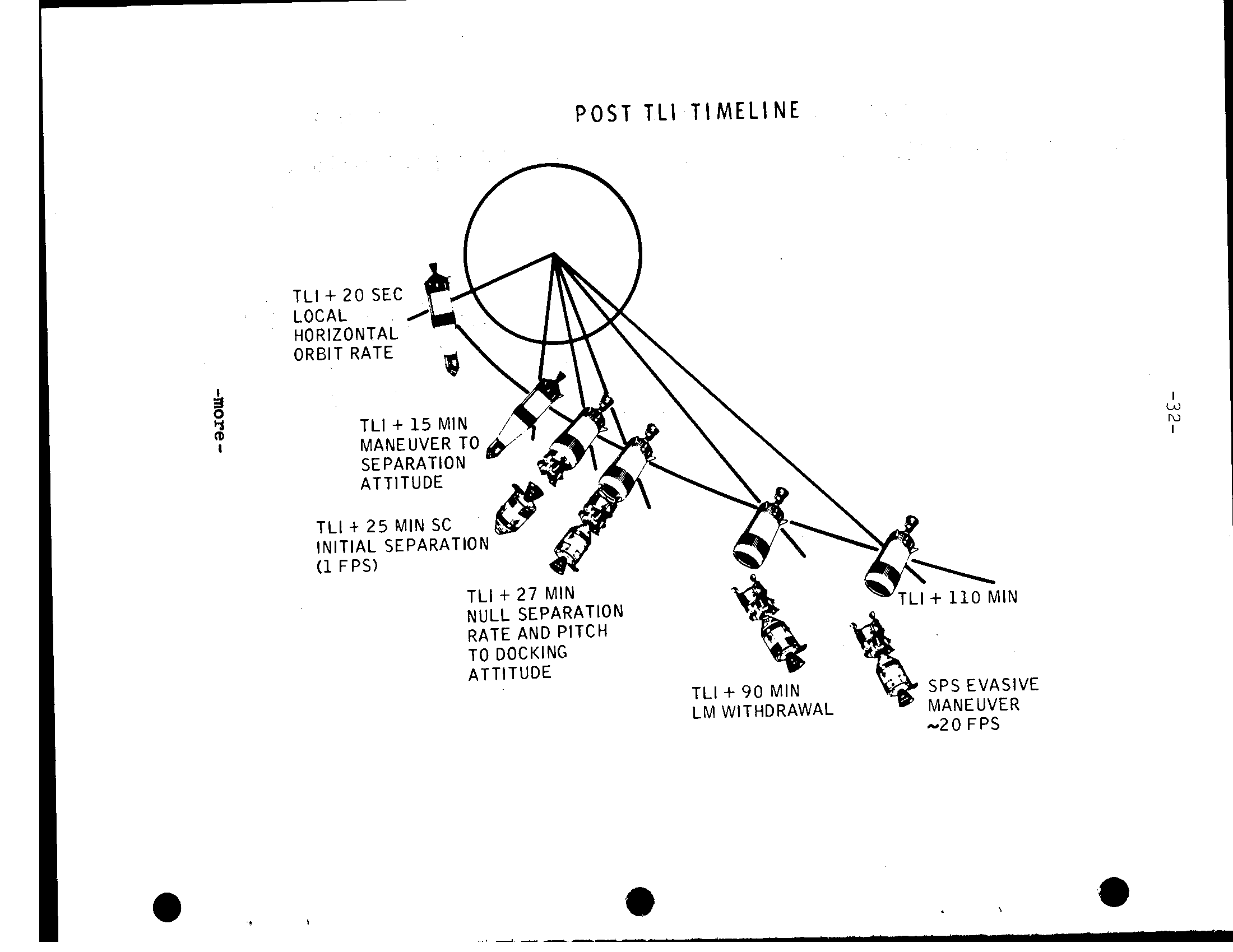
-30- The crew have backup t o launch vehicle guidance during powered f l i g h t. I f the Saturn instrument unit i n e r t i a l platform f a i l s, t h e crew can switch guidance t o t h e command module systems f o r f i r s t - s t a g e powered f l i g h t automatic control. Second and t h i r d stage b'ackup guidance through manual takeover i n which crew hand c o n t r o l l e r inputs a r e fed through the command module computer t o the Saturn instrument u n i t. Earth Parking O r b i t (EPO) Apollo w i l l remain i n Z a r t h garking o r b i t f o r one-and-one- nalf revolutions a f t e r i n s e r t i o n and w i l l hold l o c a l h o r i z o n t a l a t t i t u d e during the e n t i r e period. The crew w i l l perform spacecraft systems checks i n preparation f o r the translunar i n j e c t i o n (T L I) burn. The f i n a l"go" f o r the TLI burn w i l l be given t o the crew through the Carnarvon, Australia, Manned Space F l i g h t Network s t a t i o n. Translunar I n j e c t i o n (T L I) Midway through t h e second revolution i n Earth parking o r b i t, the S-IVB third-stage engine w i l l r e s t a r t 2:44:15 GET over the mid-Pacific j u s t south of t h e equator t o i n j e c t Apollo toward t h e Moon. The velocity w i l l increase from 25,567 fps t o 35,533 f p s TLI cutoff--a velocity increase of 9 9 1 fps. The T L I burn t a r g e t e d for about 6 f p s overspeed t o compensate for t h e l a t e r SPS evasive maneuver a f t e r LM e x t r a c t i o n. T L I w i l l place Apollo on free-return circumlunar t r a j e c t o r y from which midcourse corrections necessary could be made with t h e SM RCS t h r u s t e r s. Entry from free-return t r a j e c t o r y would be 10:37 a. m. EDT July 22 1 4. 9 degrees south l a t i t u d e by 174.9 e a s t longitude a f t e r a f l i g h t time of 145 h r s 04 min. Transposition, Docking and Ejection (TD&E) A t about three hours a f t e r l i f t o f f and 25 minutes a f t e r the T L I burn, the Apollo crew w i l l separate the command/service module from t h e spacecraft l u n a r module adapter (SLA), t h r u s t out away from t h e S-IVB, turn around and move back i n f o r docking w i t h t h e lunar module. Docking should take place a t about t h r e e hours and 2 1 minutes GET, and a f t e r the crew confirms docking l a t c h e s s o l i d l y engaged, they w i l l connect t h e CSM-to-LM umbilicals and pressurize the LM w i t h t h e command module surge tank. A t about 4:09 GET, t h e spacecraft w i l l be e j e c t e d from t h e spacecraft LM adapter by spring devices t h e four LM landing gear "knee" a t t a c h points. The e j e c t i o n springs w i l l impart about one fps velocity t o the spacecraft. A 19.7 f p s s e r v i c e propulsion system (SPS) evasive maneuver i n plane 4:39 GET w i l l separate t h e spacecraft t o s a f e distance f o r t h e S-IVB "slingshot" maneuver i n which residual launch . vehicle l i q u i d propellants w i l l be dumped through t h e J-2 engine b e l l t o propel1 the stage i n t o t r a j e c t o r y passing behind the Moon's t r a i l i n g edge and on i n t o s o l a r o r b i t. -more
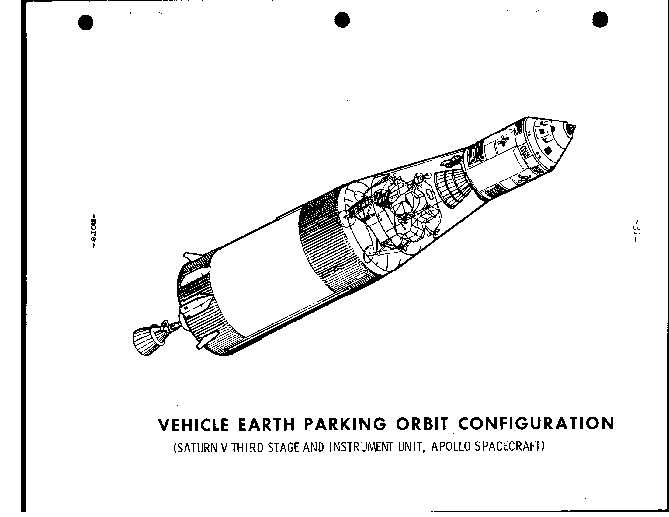
Q I c-l I VEHICLE EARTH PARKING ORBIT CONFIGURATION (SATURN V THIRD STAGE AND INSTRUMENT UNIT, APOLLO SPACECRAFT)
P O S T T L I T I M E L I N E
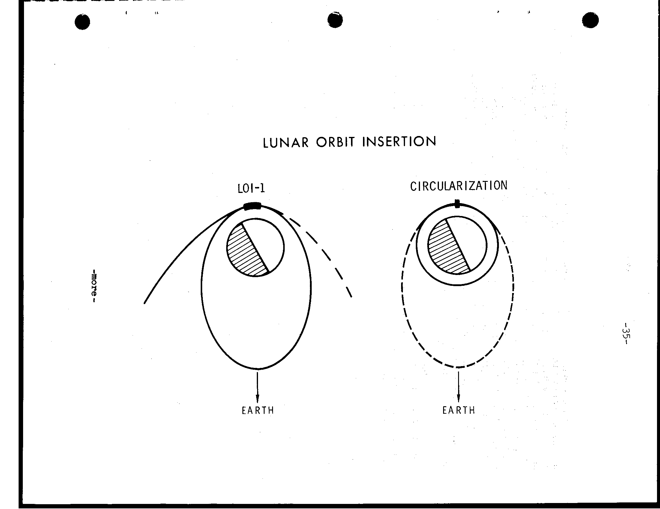
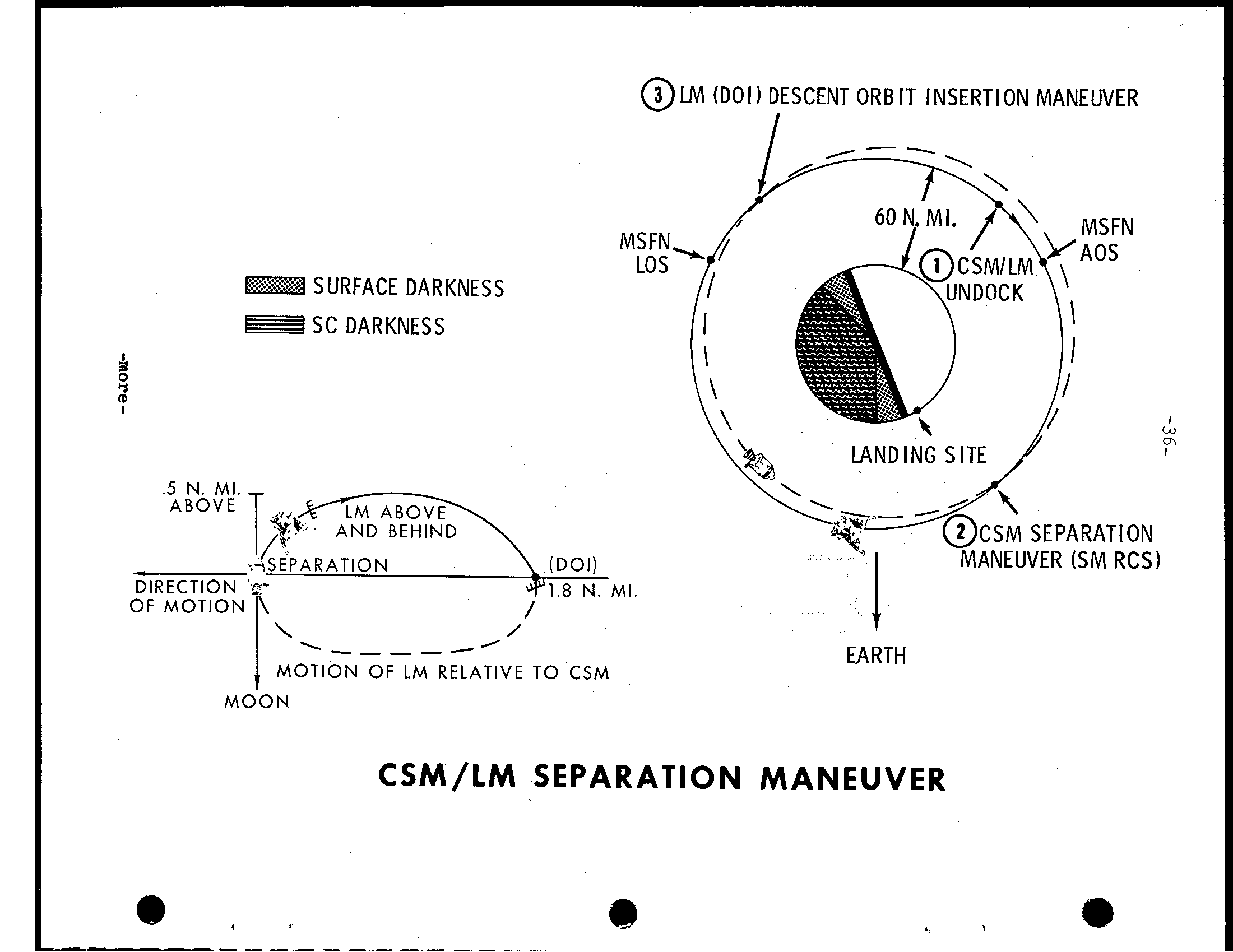
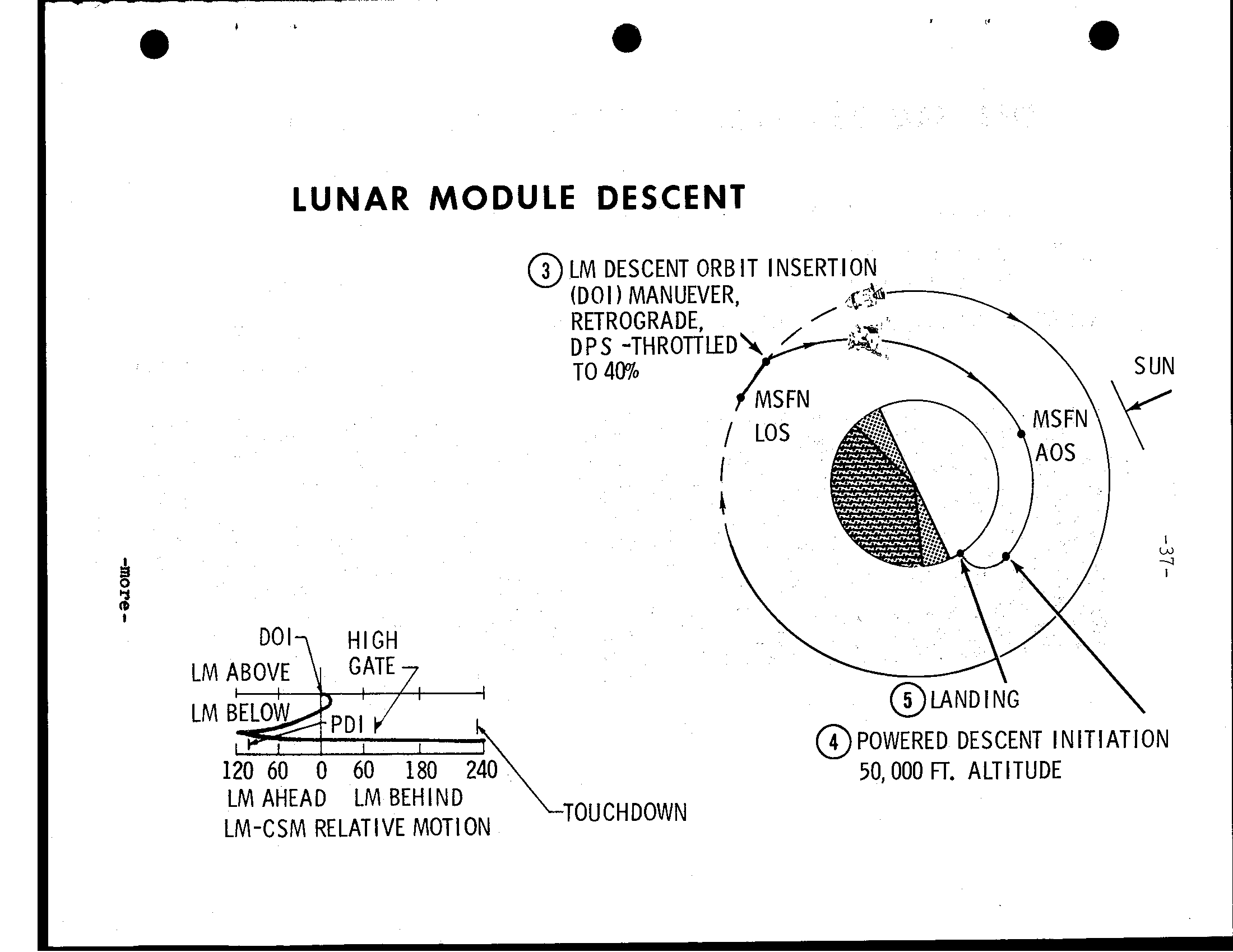
-33- e Translunar Coast Up t o four midcourse c o r r e c t i o n burns are planned d u r i n g t h e t r a n s l u n a r c o a s t phase, depending upon accuracy of t h e t r a j e c t o r y r e s u l t i n g from t h e TLI maneuver. r e q u i r e d, midcourse c o r r e c t i o n burns planned T L I +9 hours, TLI +24 hours, l u n a r o r b i t i n s e r t i o n (L O I) -22 hours and L O 1 -5 hours. During c o a s t p e r i o d s betvieen midcourse c o r r e c t i o n s, t h e s p a c e c r a f t w i l l be i n t h e p a s s i v e thermal c o n t r o l (PTC) or "barbecue" mode i n which t h e s p a c e c r a f t w i l l r o t a t e slowly about one a x i s t o s t a b i l i z e s p a c e c r a f t tnermal response t o t h e continuous s o l a r exposure. Lunar O r b i t I n s e r t i o n (LOI) The of two l u n a r o r b i t i n s e r t i o n burns w i l l be made at 75:54:28 GET at an a l t i t u d e of about 80 nm above t h e Moon. LOI-1 w i l l have nominal r e t r o g r a d e v e l o c i t y change of 2,924 f p s and w i l l i n s e r t Apollo i n t o 60x170-nm e l l i p t i c a l l u n a r o r b i t. LOI-2 two o r b i t s l a t e r 80:09:30 GET w i l l a d j u s t t h e o r b i t to a 54x65-nm o r b i t, which because of p e r t u r b a t i o n s of t h e l u n a r g r a v i t a t i o n a l p o t e n t i a l, w i l l become c i r c u l a r 60 nm t h e time of rendezvous w i t h t h e LM. The burn w i l l be 157.8 f p s r e t r o g r a d e. Both LO1 man- euvers w i l l be w i t h t h e SPS engine n e a r pericynthion when t h e space- c r a f t behind t h e Moon and out of c o n t a c t w i t h MSFN s t a t i o n s. LOI-2 (c i r c u l a r i z a t i o n), t h e l u n a r module p i l o t w i l l e n t e r t h e l u n a r module for checkout and r e t u r n t o t h e command module. Lunar Module3escent.. Lunar Landing The l u n a r module w i l l be manned and checked o u t for undock- i n g and subsequent l a n d i n g on t h e l u n a r s u r f a c e Apollo 2. Undocking w i l l t a k e p l a c e 100:09:50 GET p r i o r to MSFN a c q u i s i t i o n of s i g n a l. A readially downward s e r v i c e module RCS burn of 2. 5 f p s w i l l p l a c e C S M on an equiperiod o r b i t w i t h a maximum s e p a r a t i o n of 2.2 nm one r e v o l u t i o n a f t e r t h e s e p a r a t i o n maneuver. A t p o i n t, on l u n a r f a r s i d e, descent o r b i t i n s e r t i o n burn (D O I) w i l l be made w i t h t h e l u n a r module descent engine f i r i n g r e t r o g r a d e 7 4. 2 f p s 101:38:48 GET. The burn w i l l start a t 10 p e r c e n t t h r o t t l e for 15 seconds and t h e remainder 40 p e r c e n t t h r o t t l e. The D O 1 maneuver lowers LM p e r i c y n t h i o n t o 50,000 f e e t 2 p o i n t about 1 4 degrees uprange of l a n d i n g s i t e 2. -more-
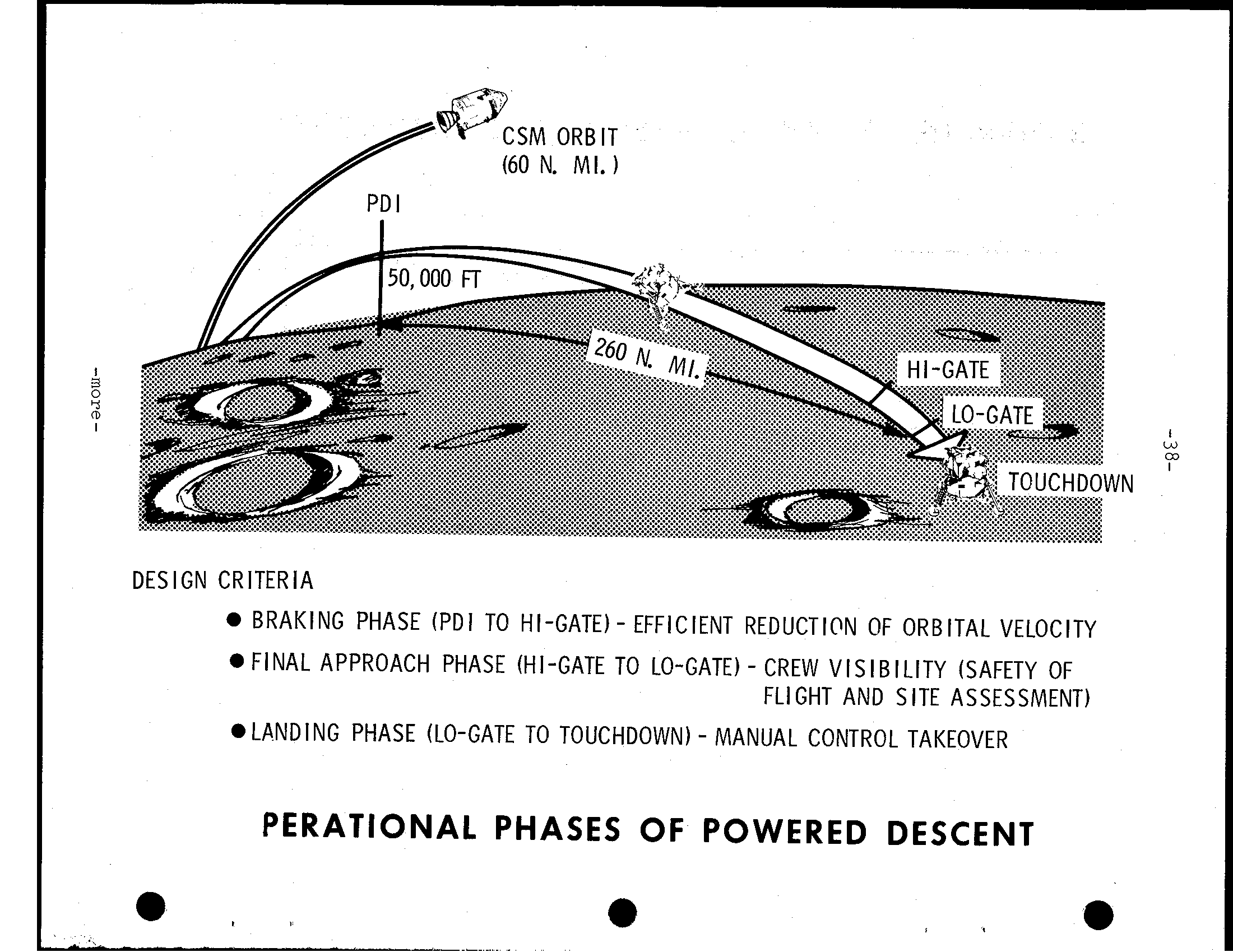
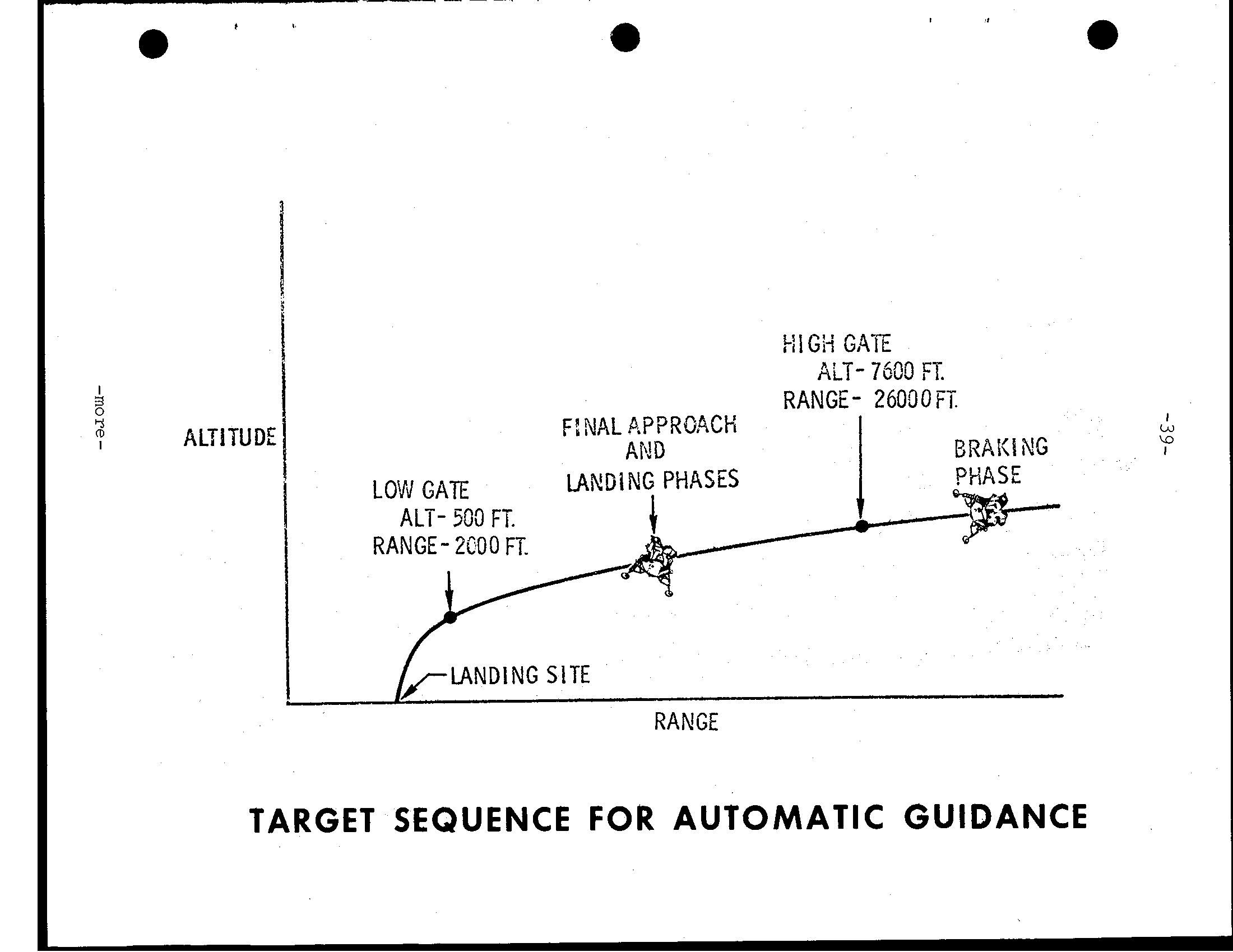
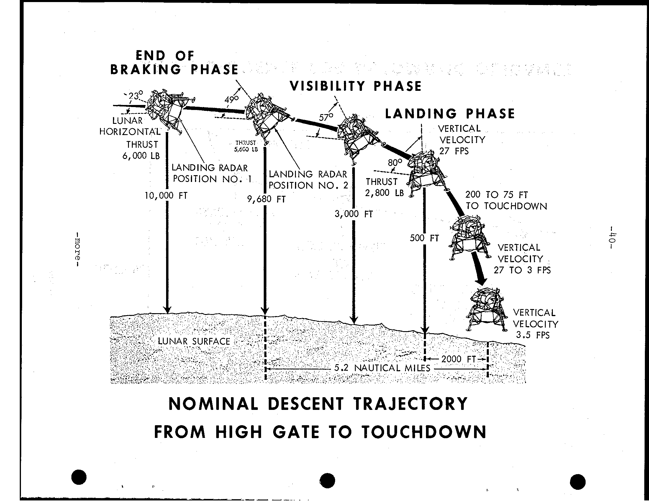
-34- A three-phase powered descent i n i t i a t i o n (PDI) maneuver begins pericynthion at 102:53:13 GET using the LM descent engine t o brake the vehicle out of the descent t r a n s f e r o r b i t. The guid- ance-controlled PDI maneuver about 260 nm p r i o r t o touchdown, and i n retrograde a t t i t u d e t o reduce velocity t o e s s e n t i a l l y zero the time v e r t i c a l descent begins. Spacecraft a t t i t u d e s range from windows down t h e of PDI, t o windows up as the spacecraft reaches 45,000 f e e t above the lunar surface and LM landing radar data can be integrated by the LM guidance computer. The braking phase ends about 7,000 f e e t above the surface and the spacecraft rotated t o an upright windows-forward a t t i t u d e. The of the approach phase called high gate, and the s t a r t of the landing phase 500 f e e t called low gate. Both the approach phase and landing phase allow p i l o t take- over from guidance control well visual evaluation of the land- i n g s i t e. The f i n a l v e r t i c a l descent t o touchdown begins about 150 f e e t when forward velocity nulled out. Vertical descent w i l l be three fps. Touchdown w i l l take place a t 102:47:ll GET. -more- -
LOI-1 CIRCULARIZATION I I 1 E A R T H E A R T H
@ LM (DOI) DESCENT ORB IT INSERTION MANEUVER SURFACE DARKNESS SC DARKNESS 4 2 I LANDING SITE 5 N. MI SE PARAT I ON - ANEUVER (SM RCS) OF MOTION I EARTH MOTION OF LM RELATIVE TO CSM MOON CSM/LM SEPARATION MANEUVER I
LUNAR h\ODULE DESCENT @ L M DESCENT ORB I T INSERTION (DO1 1 MANUEVER, RETROGRADE, D P S -THROTT TO 40% ~ h\ @POWERED DESCENT INITIATION i Qo ;;1 60 la0 2io\ 50.000 FT. ALTITUDE LM AHEAD L M BEHIND LM-CSM RELATIVE MOTION
CSM ORBIT (60 N. MI. 1 DES I GN CRlTER IA BRAKING PHASE (PDI TO HI-GATE) - EFFICIENT REDUCTION OF ORBITAL VELOCITY FINAL APPROACH PHASE (HI-GATE TO LO-GATE) - CREW V I S I B I L I T Y (SAFETY OF FLIGHT AND SITE ASSESSMENT) - LANDING PHASE (LO-GATE TO TOUCHDOWN) MANUAL CONTROL TAKEOVER PERATIONAL PHASES OF POWERED DESCENT *
!-I I GH GATE AiT- 7630 FT. RANGE- 260.30FT. i3, I 2 ALTITUDE I I ALT- 503 FT. FT. RANGE- 2COO RANGE TARGET SEQUENCE FOR AUTOMATIC GUIDANCE
END OF BRAKING PHASE NOMINAL DESCENT TRAJECTORY FROM HIGH GATE TO TOUCHDOWN Q
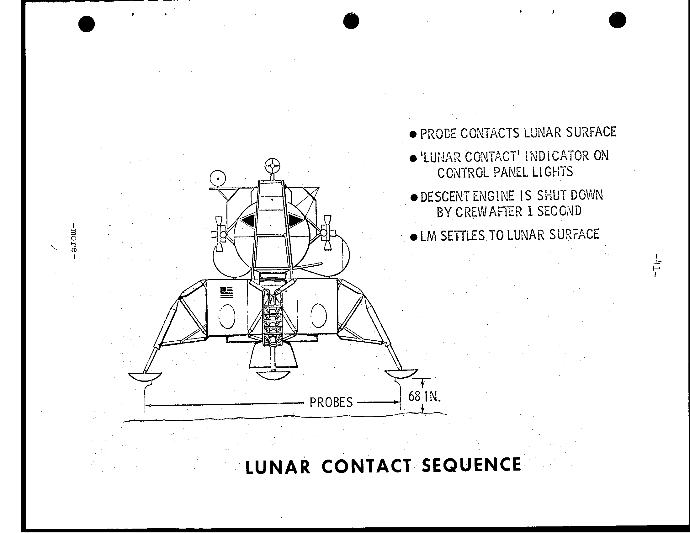
e I P R X Z CWTACTS LUNAR SURFACE 'LUidA? CCNTACT' iblDiCA70R ON CONTROL P A E L Ll G!-ITS DESCENT E i G I N E IS SiNT DGVJN BY CREWAFIZ!? I SECG4D LM SEi7LES TO LUNAR Sil!GACE J, \ r , LUNAR CONTACT SEQUENCE
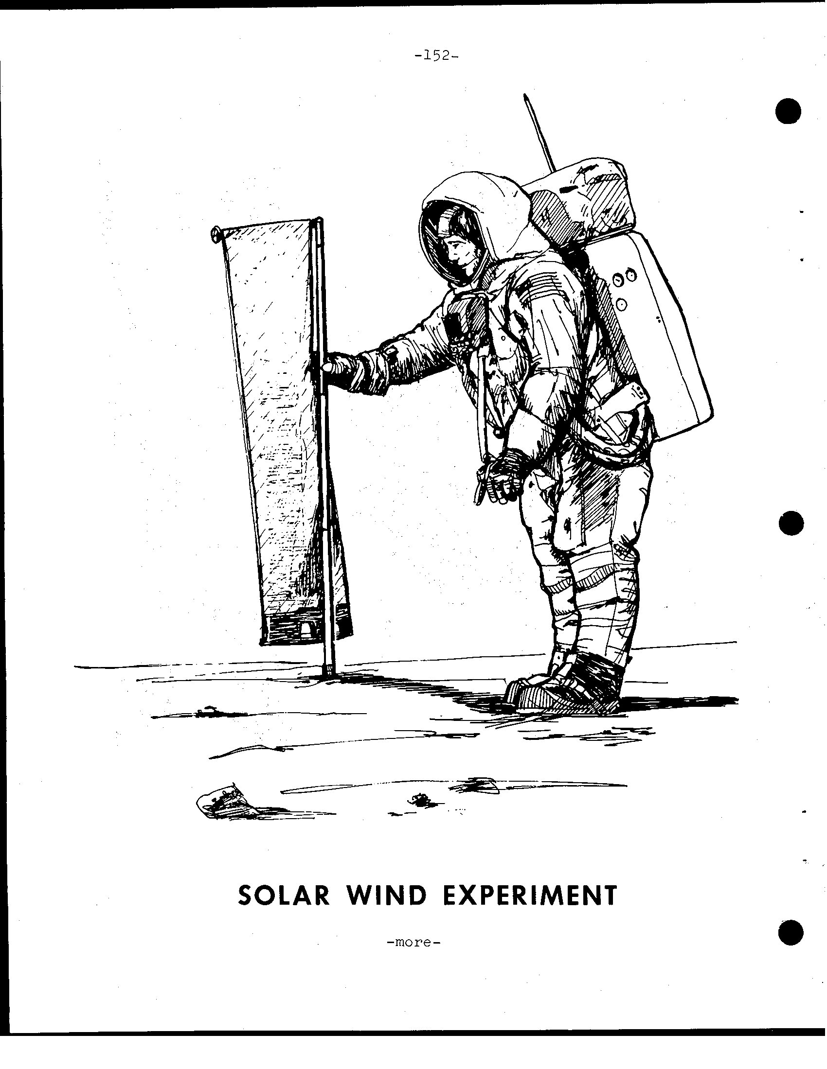
-42- Lunar Surface Extravehicular Activity (EVA) Armstrong and Aldrin will spend about 22 hours on the lunar surface after lunar module touchdown at 102:47:11 GET. Following extensive checkout of LM systems and prepara- tions for contingency ascent staging, the LM crew will eat and rest before depressurizing the LM for lunar surface EVA. Both crewmen will don portable life support system (PLSS) backpacks with oxygen purge system units (OPS) attach- ed. LM depressurization is scheduled for 112:30 GET with the commander being the first to egress the LM and step onto the lunar surface. His movements will be recorded on still and motion picture film by the lunar module pilot and by TV de- ployed by the commander prior to descending the ladder. The LM pilot will leave the LM about 25 minutes after the com- mander and both crewmen will collect samples of lunar material and deploy the Early Apollo Scientific Experiments Package (EASEP) and the solar wind composition (SWC) experiment. The commander, shortly after setting foot on the lunar surface, will collect a contingency sample of surface mater- ial and place it in his suit pocket. Later both crewmen will collect as much as 130 pounds loose materials and core samples which will be stowed in air-tight sample return con- tainers f o r return to Earth. Prior to sealing the SRC, the SWC experiment, which measures the elemental and isotopic constituents of the noble (inert) gases in the solar wind, is rolled up and placed in the container for return to Earth for analysis. Principal ex- perimenter is D r. Johannes Geiss, University of Bern, Switzerland. The crew will photograph the landing site terrain and inspect the LM during the EVA. They can range out to about 100 feet from the LM. After both crewmen have ingressed the LM and have con- nected to the cabin suit circuit, they will doff the PLSS backpacks and jettison them along with other gear no longer needed, through the LM front hatch onto the lunar surface. The LM cabin will be repressurized about 2 hrs. 40 min. after EVA initiation to permit transfer by the crew to the LM life support systems. The LM will then be depressurized to jettison unnecessary equipment to the lunar surface and be repressurized. The crew will have a meal and rest period before preparing for ascent into lunar orbit and rendezvousing w i t h the CSM. -more-
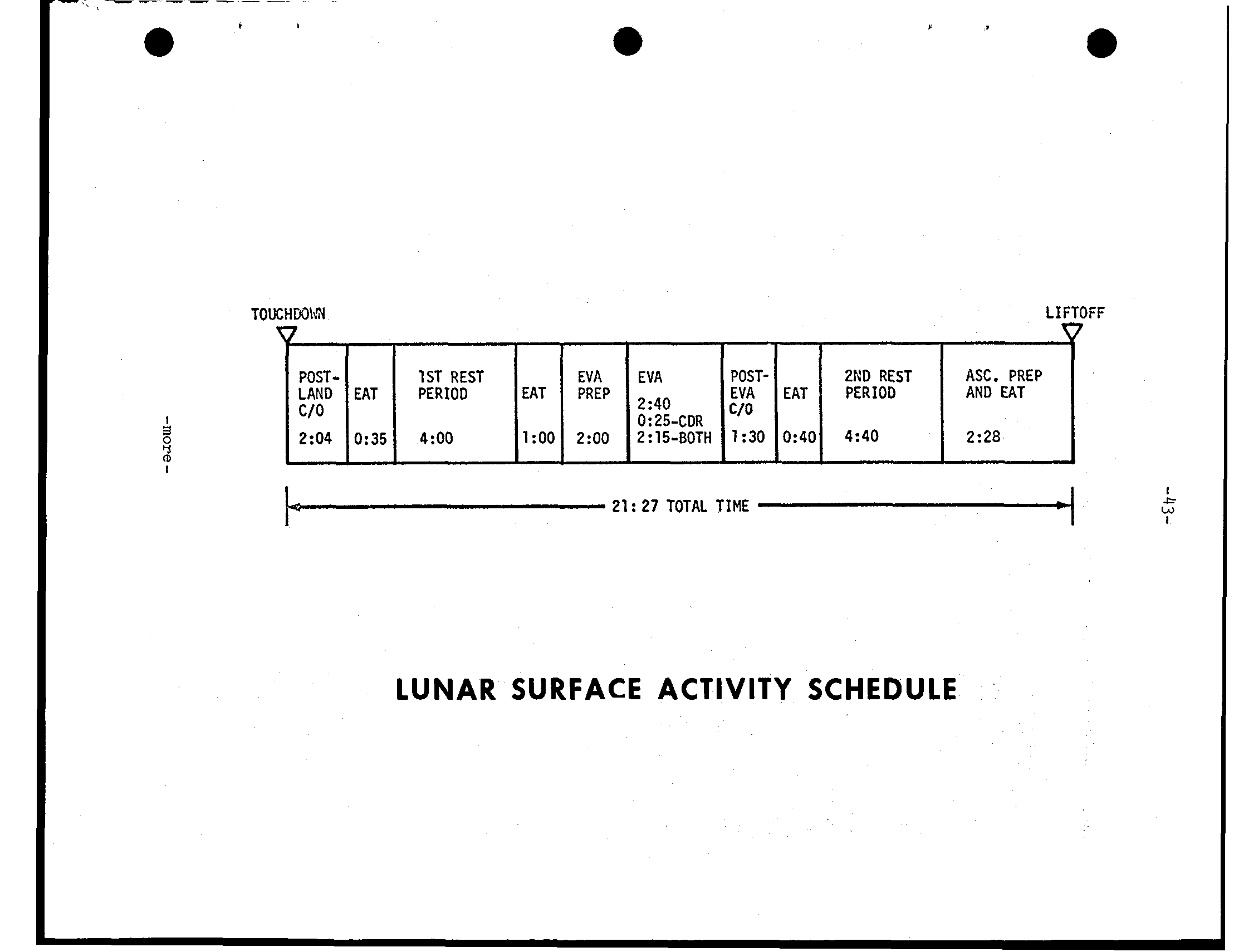
-------- * LIFTOFF POST- 1ST REST EVA EVA POST- 2ND REST ASC. PREP PERIOD EAT PREP 2:40 EVA EAT PERIOD AND EAT C/O I 0:25-CDR 4:OO 1:OO 2:OO 2:15-BOTH 1 ~ 3 0 0 ~ 4 0 4:40 2:28 2 I 21 27 TOTAL IME 4= ' - - / I LUNAR SURFACE ACTIVITY SCHEDULE
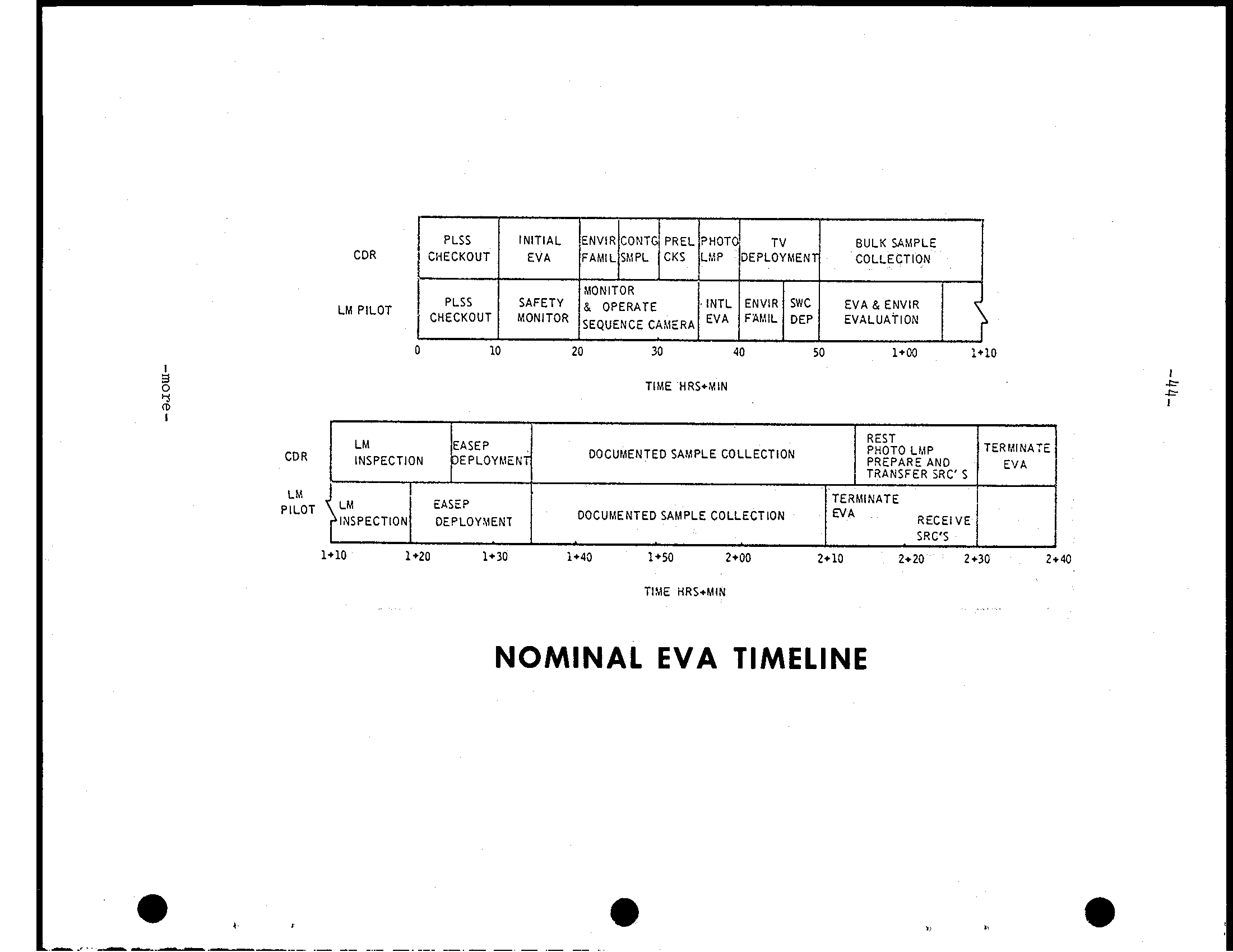
PLSS INITIAL ENVIR CONTG PREL PHOTO T V BULK SAMPLE CDR CHECKOUT EVA FAMIL SMPL CKS LI!P DEPLOYMENT COLLECTION MONITOR PLSS SAFETY 8 OPERATE INTL ENVlR SWC E V A & ENVlR LM PILOT CHECKOUT MONITOR SEQUENCE CAhlERA EVA F A M L DEP EVALUATION - I REST LM EASEP PHOTO LMP TERMINATE CDR DOCUMENTED SAMPLE COLLECTION INSPECTION DEPLOYMENT PREPARE AND EVA TRANSFER SRC' 5 LM TERMINATE EASEP PILOT LM DOCUMENTED SAMPLE COLLECTION EVA INSPECTION DEPLOY\!ENT RECEIVE SRC'S TIME HRSIMIN NOMINAL EVA TIMELINE
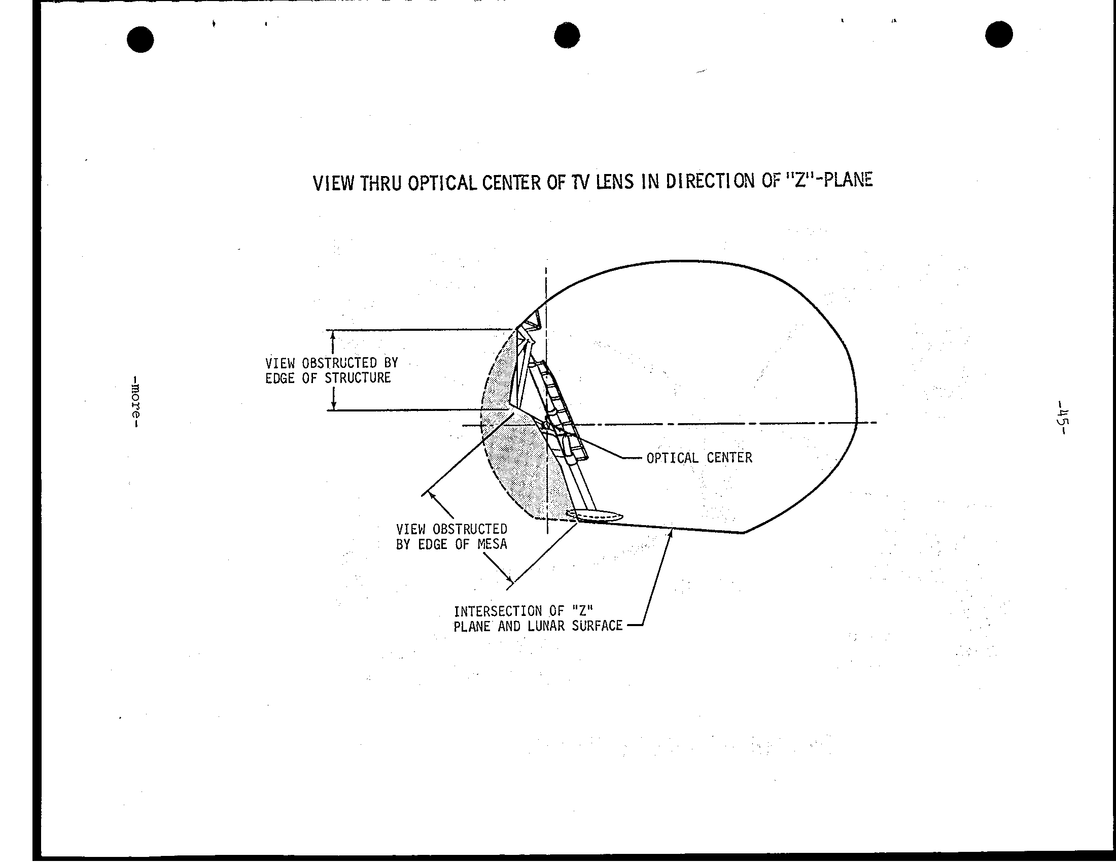
e VIEW T i R U OPTICAL CENTER OF N LENS IN DIRECT1 ON OF "Z"-PLANE VIEW EDGE INTERSECTION OF "Z" PLANE AND LUNAR SURFACE
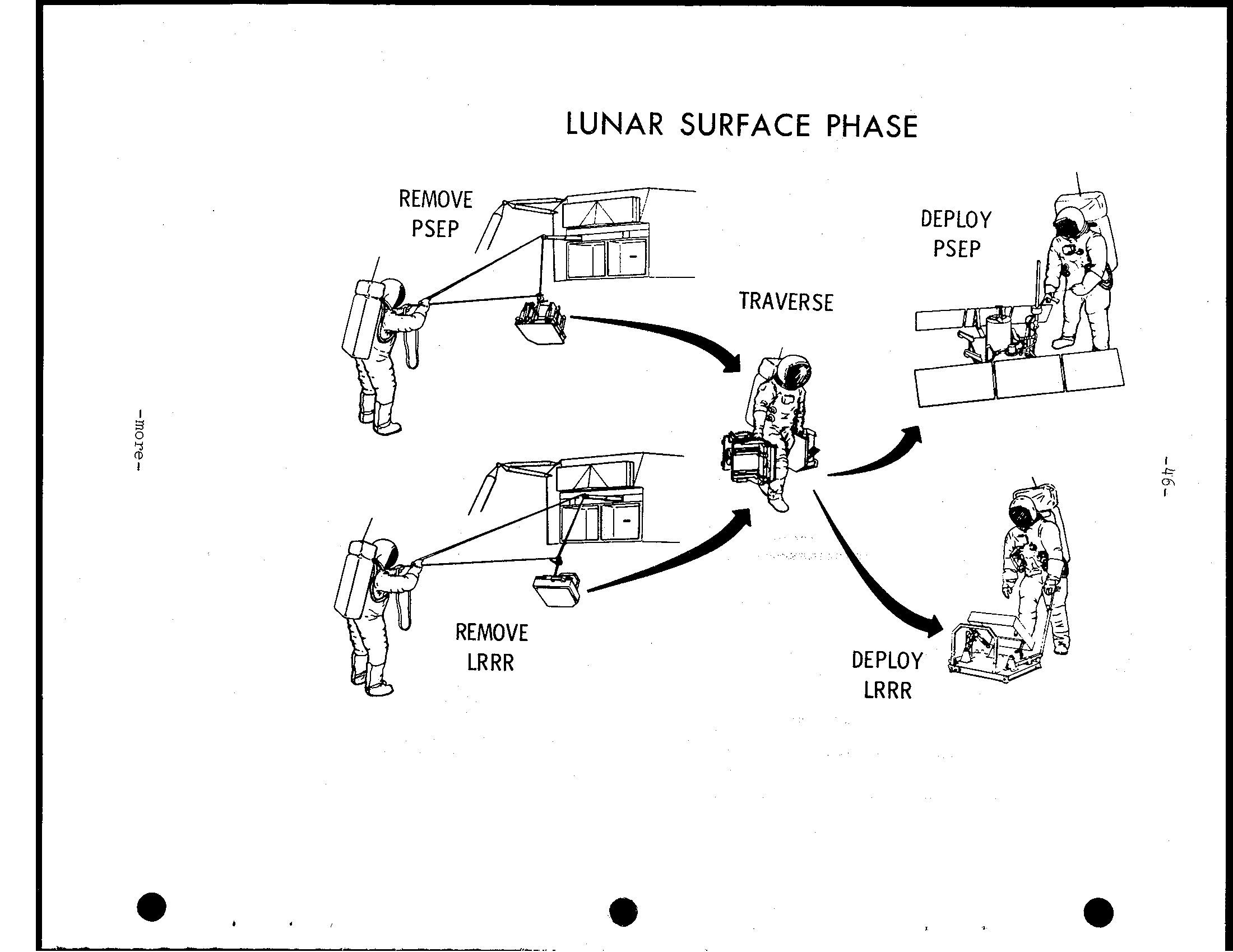
LUNAR SURFACE PHASE 2 I
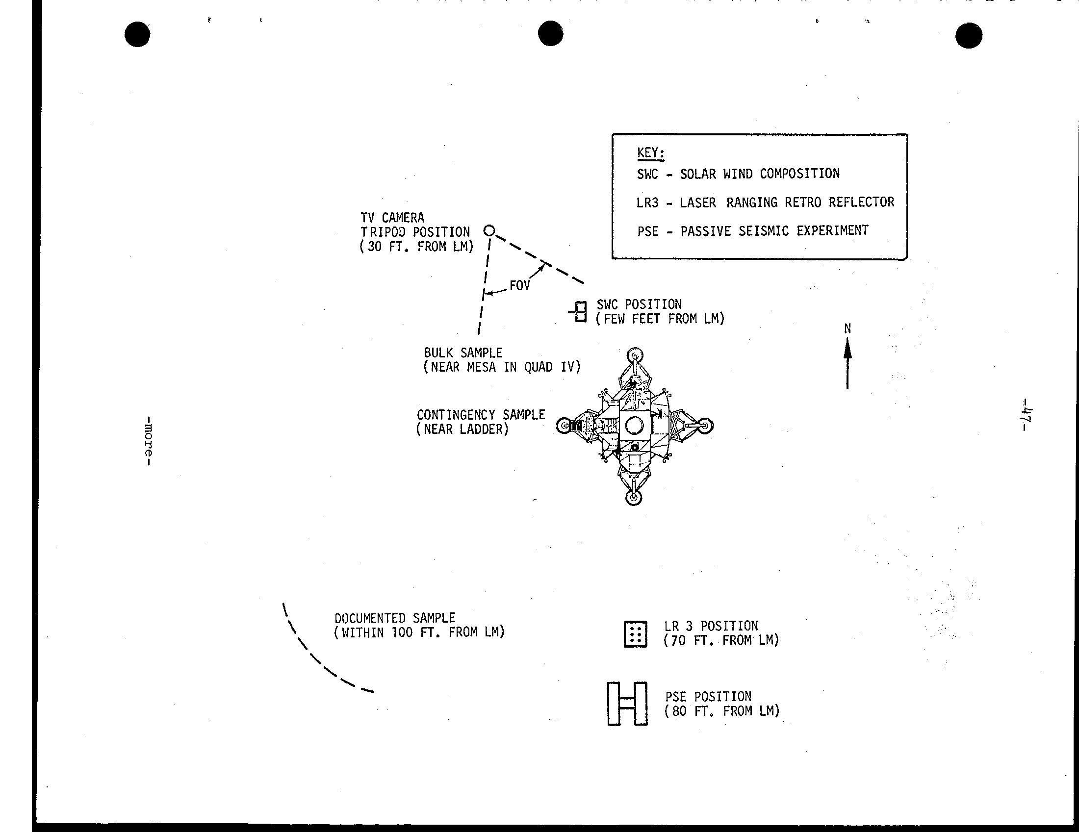
KEY: - SMC SOLAR WIND COMPOSITION I - I L R 3 LASER RANGING RETRO REFLECTOR TV CAMERA - TRIPOD POSITION PSE PASSIVE SEISMIC EXPERIMENT (30 FT. FROM LM) 1- SWC POSITION I -8 (FEW FEET FROM LM) I N BULK SAMPLE (NEAR MESA IN QUAD IV) CONTINGENCY SAMPLE (NEAR LADDER) \ DOCUMENTED SAMPLE LR 3 POSITION (W I T H I N 100 FT. FROM LM) (70 FT. FROM LM) PSE POSITION (80 FT. FROM LM)
-4 8- Lunar Sample Collection Equipment for collecting and stowing lunar surface samples is housed in the modularized equipment stowage assembly (MESA) on the LM descent stage. The commander will unstow the equip- ment after adjusting to the lunar surface environment. Items stowed in the MESA are as follows: * Black and white TV camera. * Large scoop for collecting bulk and documented samples of loose lunar surface material. * Extension handle that fits the large scoop, core tubes and hammer. * Tongs for collecting samples of rock and for picking up dropped tools. * Gnomon for vertical reference, color and dimension scale for lunar surface photography. * Hammer for driving core tubes, chipping rock and for trenching (with extension handle attached). * 35mm stereo camera * Two sample return containers (SRC) for returning up to l3O pounds of bulk and documented lunar samples. Items such as large and small sample bags, core tubes, gas analysis and lunar environment sample containers are stowed in the SRCs. Both containers are sealed after samples have been collected, docu- mented and stowed, and the crew will hoist them into the ascent stage by means of an equipment conveyor for transfer into the command module and subsequent return to Earth for analysis in the Lunar Receiving Laboratory. Additionally, a contingency lunar sample return container is stowed in the LM cabin for use by the commander during the early phases of his EVA. The device is a bag attached to an extending handle in which the commander will scoop up about one liter of lunar material. He then will jettison the handle and stow the contingency sample in his pressure suit pocket.
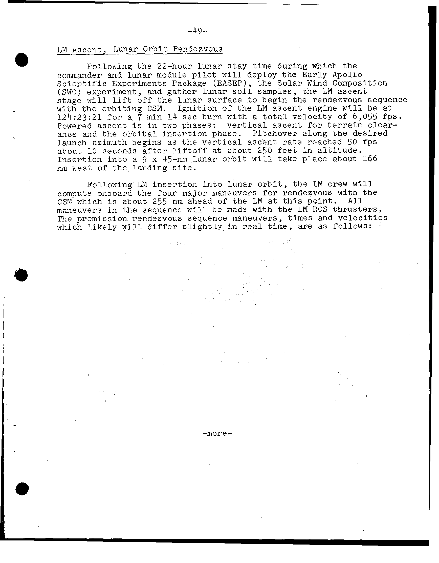
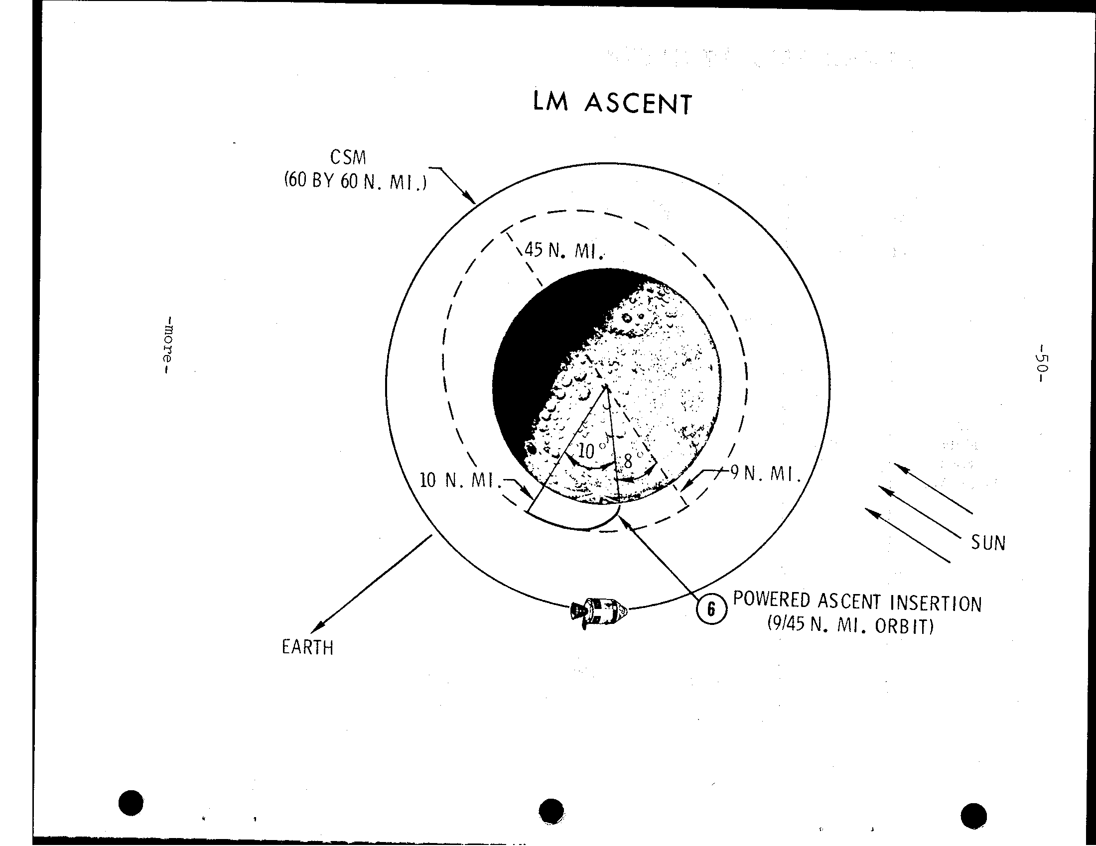
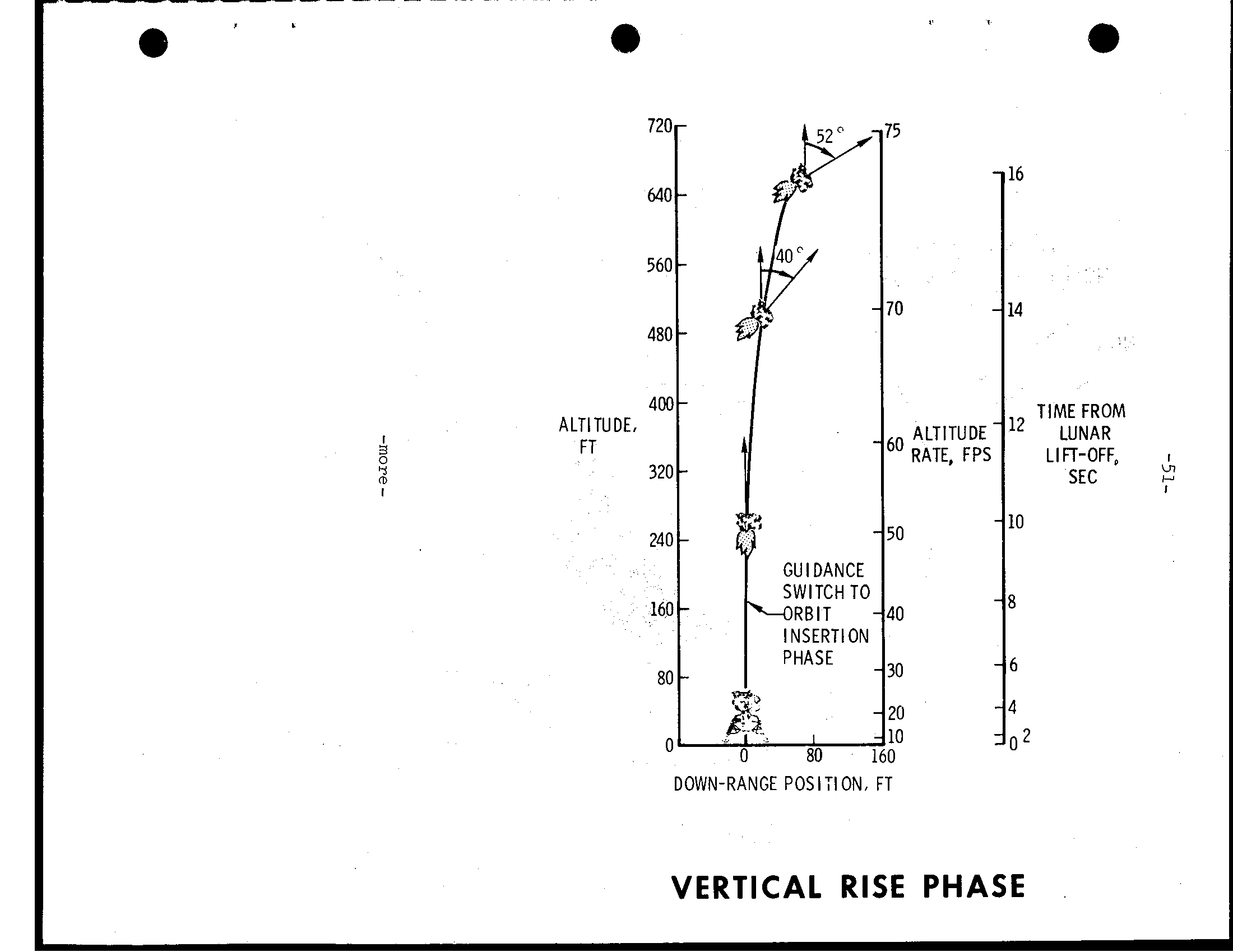
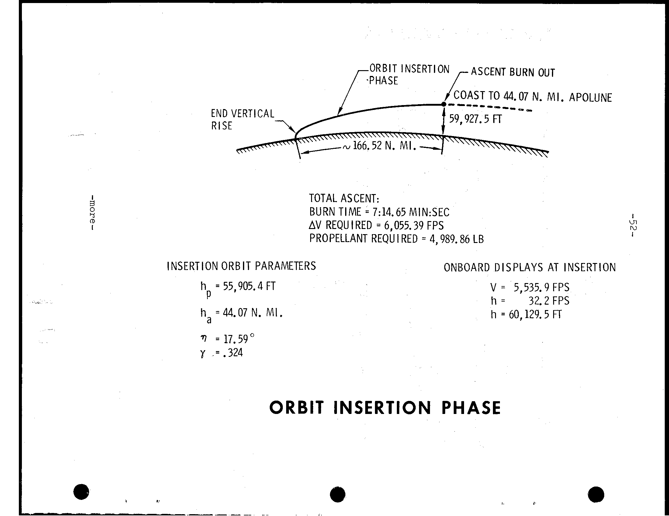
-49- LM Ascent, Lunar O r b i t Rendezvous Following t h e 22-hour lunar s t a y time during which t h e commander and lunar module p i l o t w i l l deploy the E a r l y Apollo S c i e n t i f i c Experiments Package (EASEP), the Solar Wind Composition (SWC) experiment, and gather lunar s o i l samples, the LM ascent w i l l off lunar surface t o begin rendezvous sequence with o r b i t i n g CSM. Ignition of LM ascent engine w i l l be at 124:23:21 f o r 7 min 1 4 see burn with t o t a l velocity of 6,055 f p s. Powered ascent i n two phases: v e r t i c a l ascent f o r t e r r a i n clear- ance and the o r b i t a l i n s e r t i o n phase. Pitchover along desired launch azimuth begins t h e v e r t i c a l ascent r a t e reached 50 f p s about 1 0 seconds a f t e r l i f t o f f about 250 f e e t i n a l t i t u d e. Insertion i n t o 9 x 45-nm lunar o r b i t w i l l take place about 166 nm west of the landing s i t e. Following LM i n s e r t i o n i n t o lunar o r b i t, t h e LM crew w i l l compute onboard the four major maneuvers f o r rendezvous with the CSM which about 255 nm ahead of the LM t h i s point. A l l maneuvers i n the sequence w i l l be made with the LM RCS t h r u s t e r s. The premission rendezvous sequence maneuvers, times and v e l o c i t i e s which l i k e l y w i l l d i f f e r s l i g h t l y i n r e a l time, are follows: I I I I - -more-
LM ASCENT I + S U N POWERED ASCENT INSERTION (9145 N. MI. O R B I T) EARTH c
a a r5 TIME FROM LUNAR LIFT-OFF, SEC GU I DANCE SWITCH T( I NSERTIOh PHASE DOWN-RANGE POSITION, FT VERTICAL RISE PHASE
/COAST TO 44.07 N. MI. APOLUNE - - -- -------- f 59,927.5 FT TOTAL ASCENT: BURN TIME 7:14.65 MIN:SEC = AV REQUIRED 6,055.39 FPS = PROPELLANT REQU RED 4,989.86 LB = INSERTION ORBIT PARAMETERS ONBOAXD DISPLAYS AT INSERTION h 55,905.4 FT V 5,535.9 FPS = = P h = 32.2 FPS h -44.07 N. MI. h 60,129.5 FT = a ... 17.59' 7) = r .324 .= ORBIT INSERTION PHASE
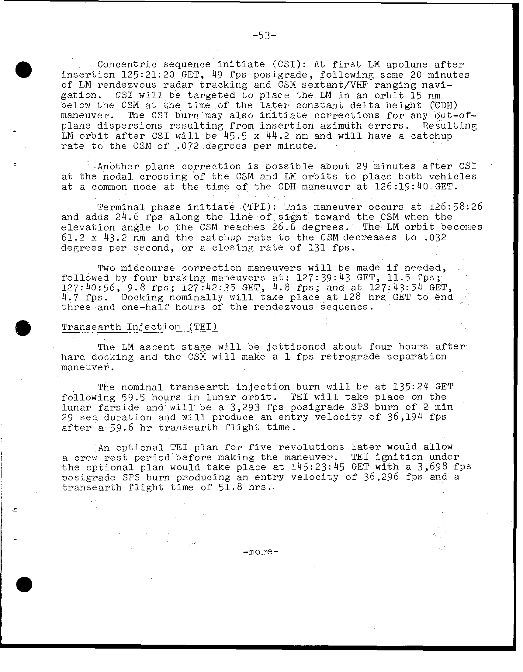
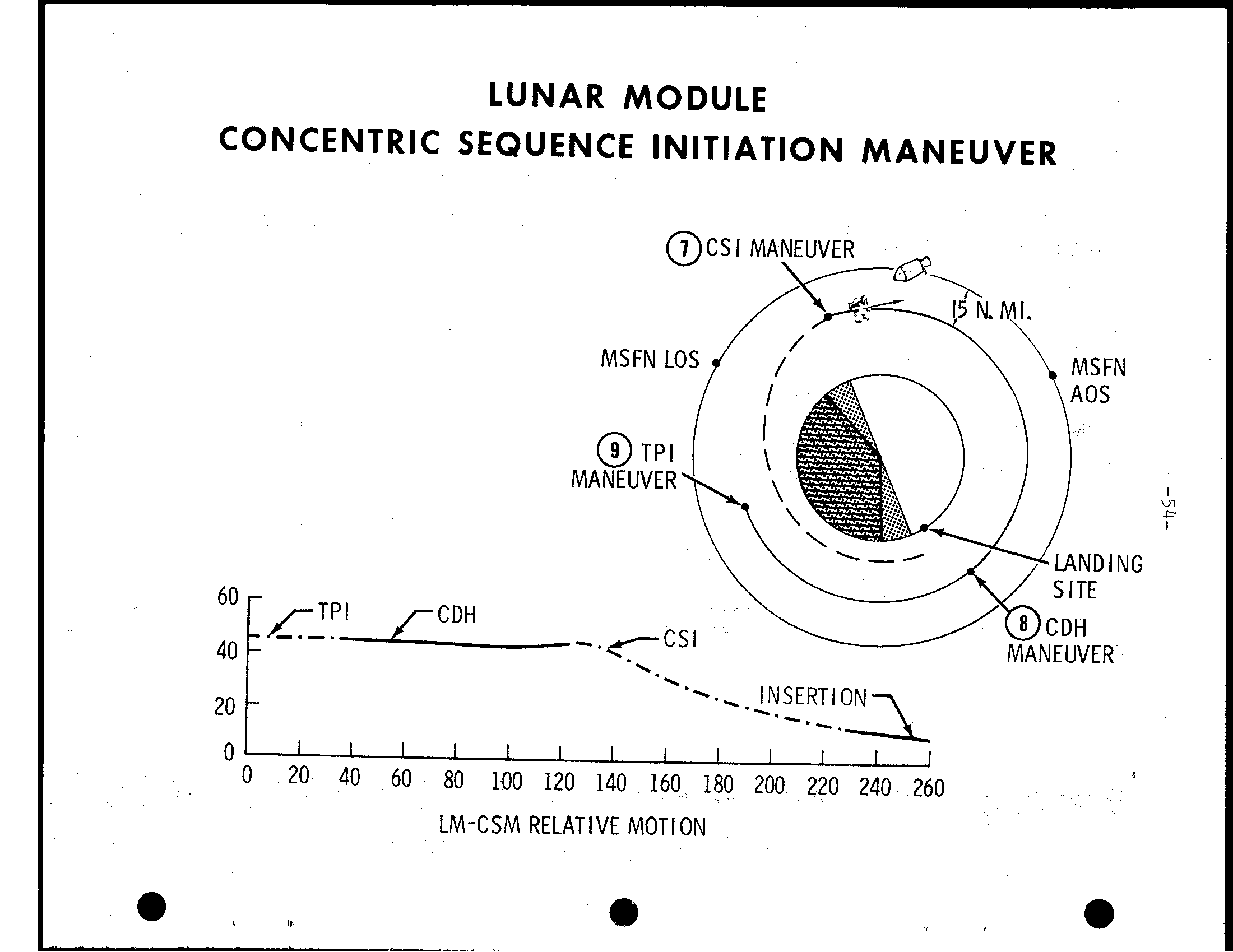
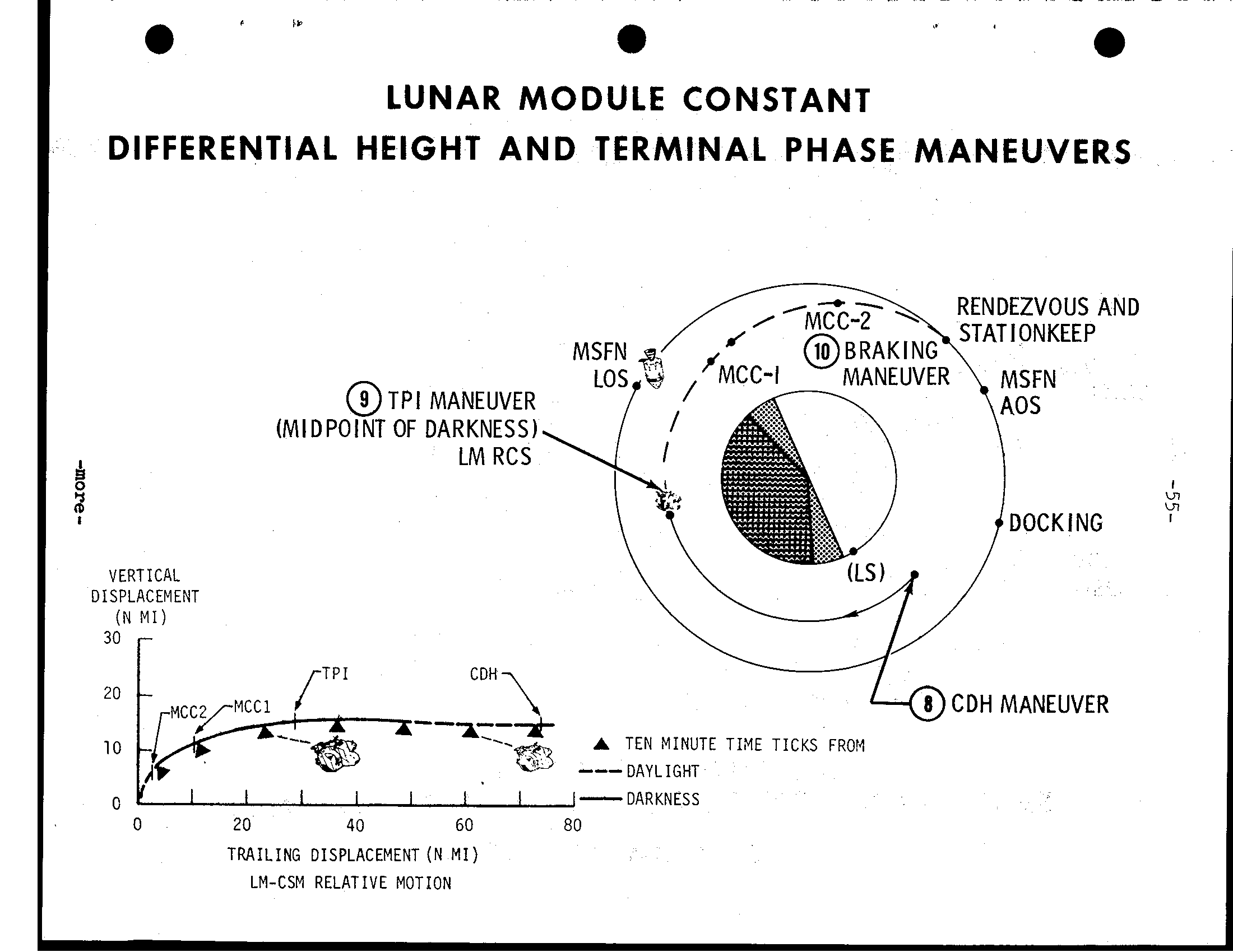
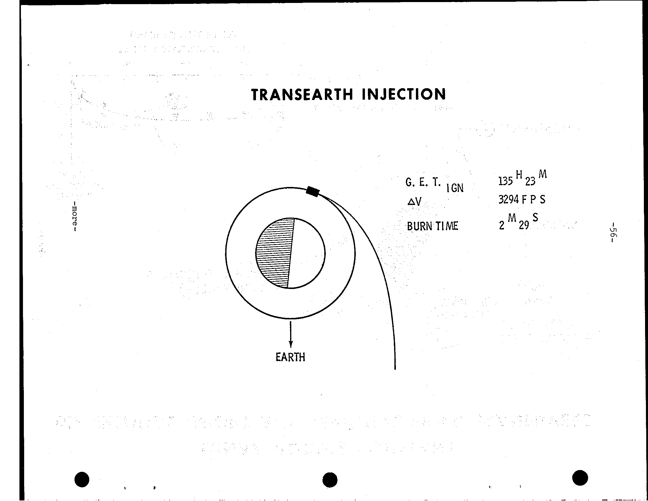
-53- Concentric sequence i n i t i a t e (CSI): A t LM apolune after i n s e r t i o n 125:21:20 GET, 49 f p s posigrade, following some 20 minutes of LM rendezvous t r a c k i n g and CSM sextant/VHF ranging navi- g a t i o n. C S I w i l l be t o place the LN i n an o r b i t 15 nm below t h e CSM the time of constant (CDH) maneuver. CSI burn may a l s o i n i l. i a t e c o r r e c t i o n s for any out-of- plane d i s p e r s i o n s r e s u l t i n g from i n s e r t i o n azimuth e r r o r s. R e s u l t i n g LM o r b i t after CSI w i l l 45.5 x 44.2 nm and w i l l have a catchup t o CSM o f .072 degrees p e r minute. Another plane c o r r e c t i o n p o s s i b l e about 29 minutes after CSI t h e nodal c r o s s i n g of CSM and LM o r b i t s t o place both v e h i c l e s a t common node at the time of t h e CDH maneuver 126:19:40 GET. Terminal phase i n i t i a t e (T P I): T h i s maneuver occurs at 126:58:26 and 24.6 f p s along l i n e of toward CSM when e l e v a t i o n angle t o the CSM reaches 26.6 LM o r b i t becomes 61.2 x 43.2 nm and the catchup r a t e t o the CSM decreases t o.032 per second, or c l o s i n g rate of 131 f p s. Two midcourse c o r r e c t i o n maneuvers w i l l be made needed, followed by f o u r braking maneuvers a t: 127:39:43 GET, 11.5 127:40:56, 9.8 f p s; 127:42:35 GET, 4.8 and 127:43:54 GET, 4. 7 Docking nominally w i l l take p l a c e at 128 GET t o and one-half hours of rendezvous sequence. Transearth I n j e c t i o n (T E I) LM ascent w i l l be j e t t i s o n e d about f o u r hours docking and CSM w i l l make f p s r e t r o g r a d e s e p a r a t i o n maneuver. The nominal t r a n s e a r t h i n j e c t i o n burn w i l l be 135:24 GET following 59.5 hours i n l u n a r o r b i t. T E I w i l l take place on l u n a r and w i l l 3,293 f p s posigrade SPS burn of 2 min 29 s e e d u r a t i o n and w i l l produce an e n t r y v e l o c i t y of 36,194 after 59.6 h r t r a n s e a r t h time. An o p t i o n a l TEI f o r r e v o l u t i o n s would allow a crew period b e f o r e making maneuver. TEI i g n i t i o n under o p t i o n a l plan would t a k e p l a c e 145:23:45 GET 3,698 f p s SPS burn producing an e n t r y v e l o c i t y of 36,296 t r a n s e a r t h f l i g h t time of 51.8 -more-
LUNAR MODULE CONCENTRIC SEQUENCE INITIATION MANEUVER 60 - CDH 40 20 0 LM-CSM RELATIVE MOTION
a LUNAR MODULE CONSTANT DIFFERENTIAL HEIGHT AND TERMINAL PHASE MANEUVERS RENDEZVOUS AND @ TPI MANEUVER (MIDPOINT OF DARKNESS 1 LM RCS VERTICAL DISPLACEMENT (N M I) 30 20 A TEN MINUTE T I N E TICKS FROr.1 10 DAYLIGHT 0 -DARKNESS 0 20 40 60 80 TRAILING DISPLACEMENT (N MI) LM-CSM RELATIVE MOTION
TRANSEARTH INJECTION 3294 F P S ZM29’ EARTH
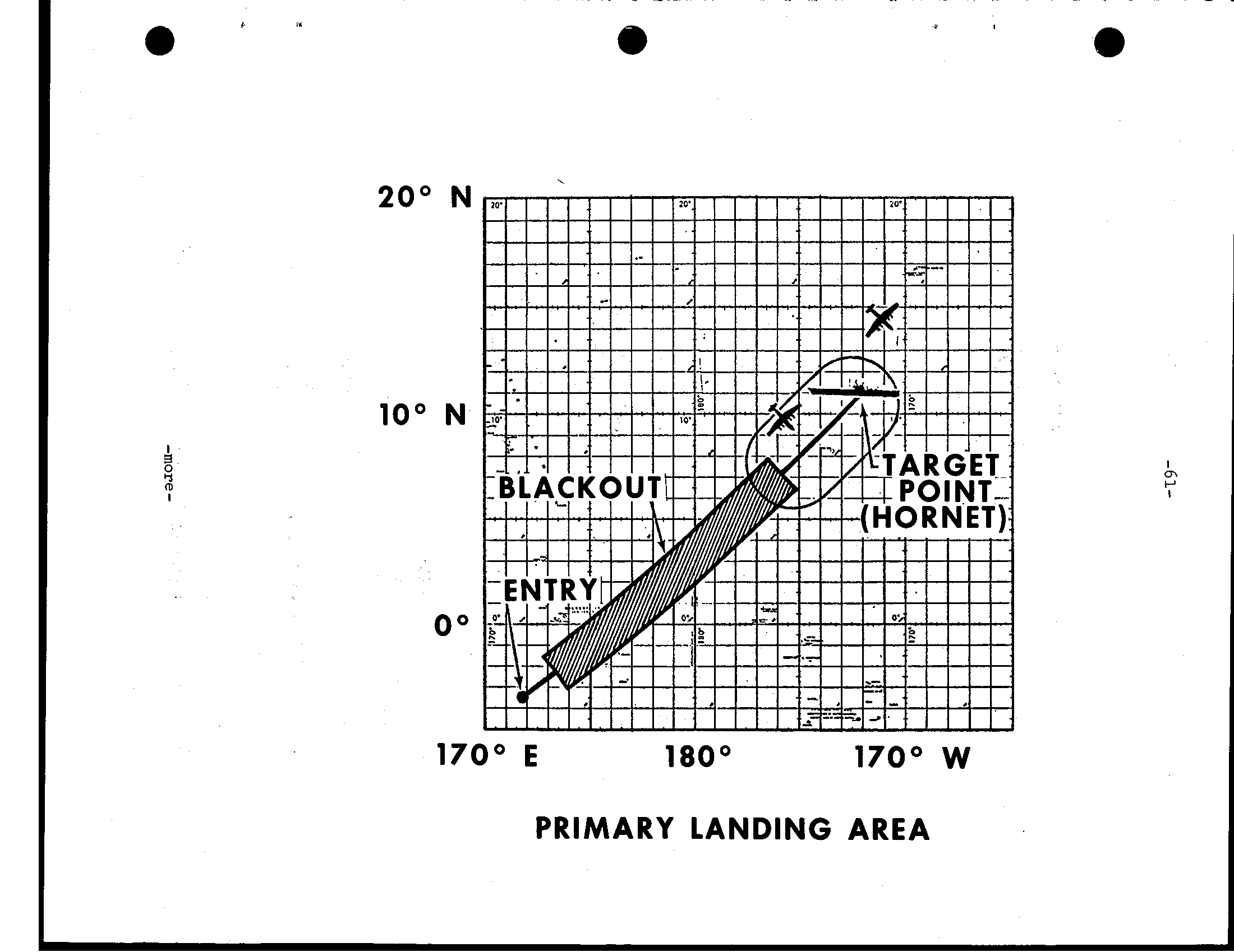
-57- Transearth coast Three corridor-control t r a n s e a r t h midcourse c o r r e c t i o n burns w i l l be made needed: MCC-5 TEI +15 h r s, MCC-6 a t I e n t r y i n t e r f a c e (EI=400,000 f e e t) -15 h r s and MCC-7 E I -3 h r s I Entry Landing I 1 - Apollo w i l l encounter t h e E a r t h's atmosphere (400,000 195:05:04 GET v e l o c i t y of 36,194 f p s and w i l l land some 1,285 nm downrange from t h e e n t r y - i n t e r f a c e p o i n t using t h e space- c r a f t's l i f t i n g c h a r a c t e r i s t i c s t o reach landing p o i n t. Touch- down w i l l at 195:19:05 10.6 degrees n o r t h l a t i t u d e by 172.4 west longitude. -more-
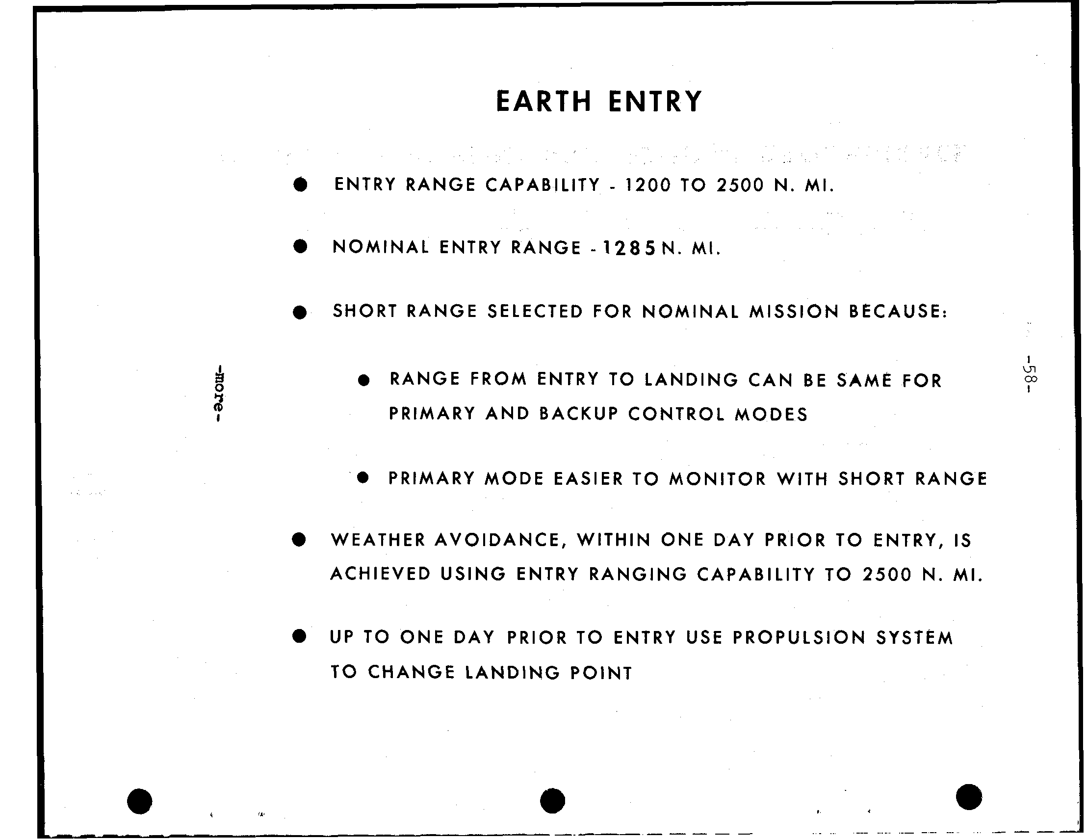
EARTH ENTRY - ENTRY RANGE CAPABILITY 1200 TO 2500 N. MI. NOMINAL ENTRY RANGE - 1 2 8 5 N. SHORT RANGE SELECTED FOR NOMINAL MISSION BECAUSE: I RANGE FROM E N T R Y TO LANDING CAN B E SAME FOR co I PRIMARY AND BACKUP CONTROL MODES PRIMARY MODE EASIER TO MONITOR WITH SHORT RANGE WEATHER AVOIDANCE, WITHIN ONE DAY PRIOR TO ENTRY, I S ACHIEVED USING ENTRY RANGING CAPABILITY TO 2500 N. MI. UP TO ONE DAY PRIOR TO ENTRY USE PROPULSION SYSTEM TO CHANGE LANDING POINT
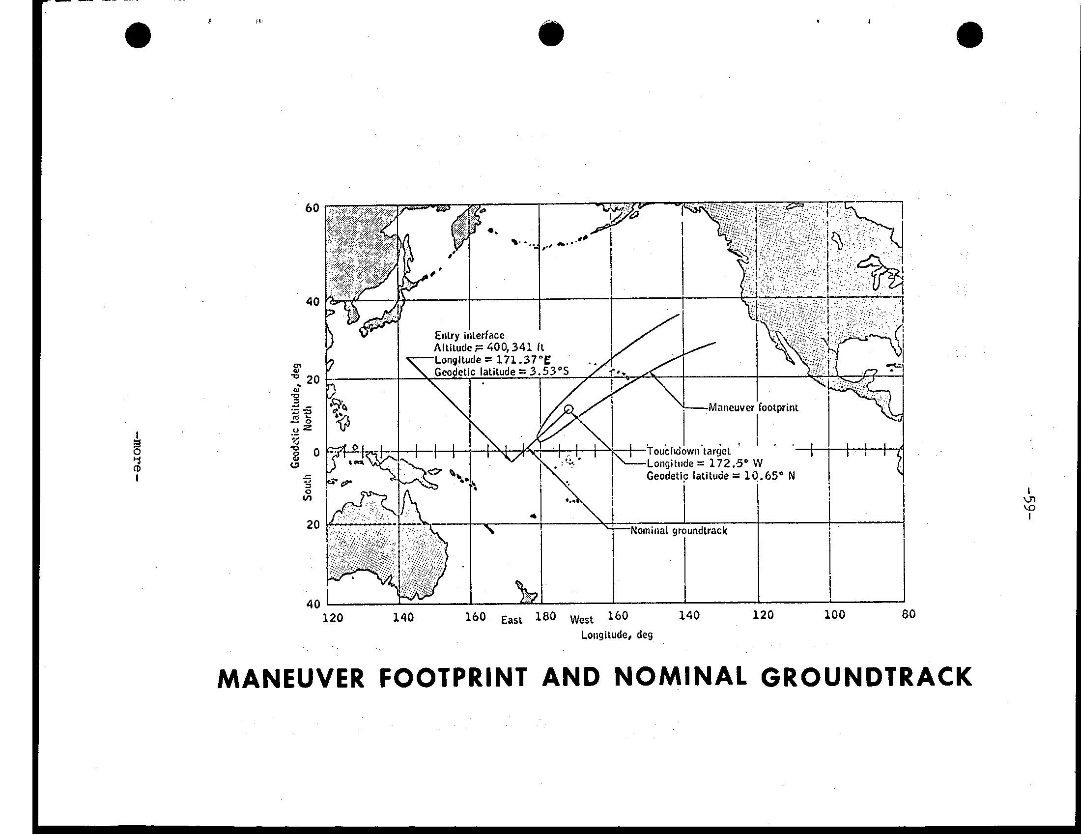
140 120 100 80 120 140 160 East 180 West 160 Loiigitude, deg MANEUVER FOOTPRINT AND NOMINAL GROUNDTRACK
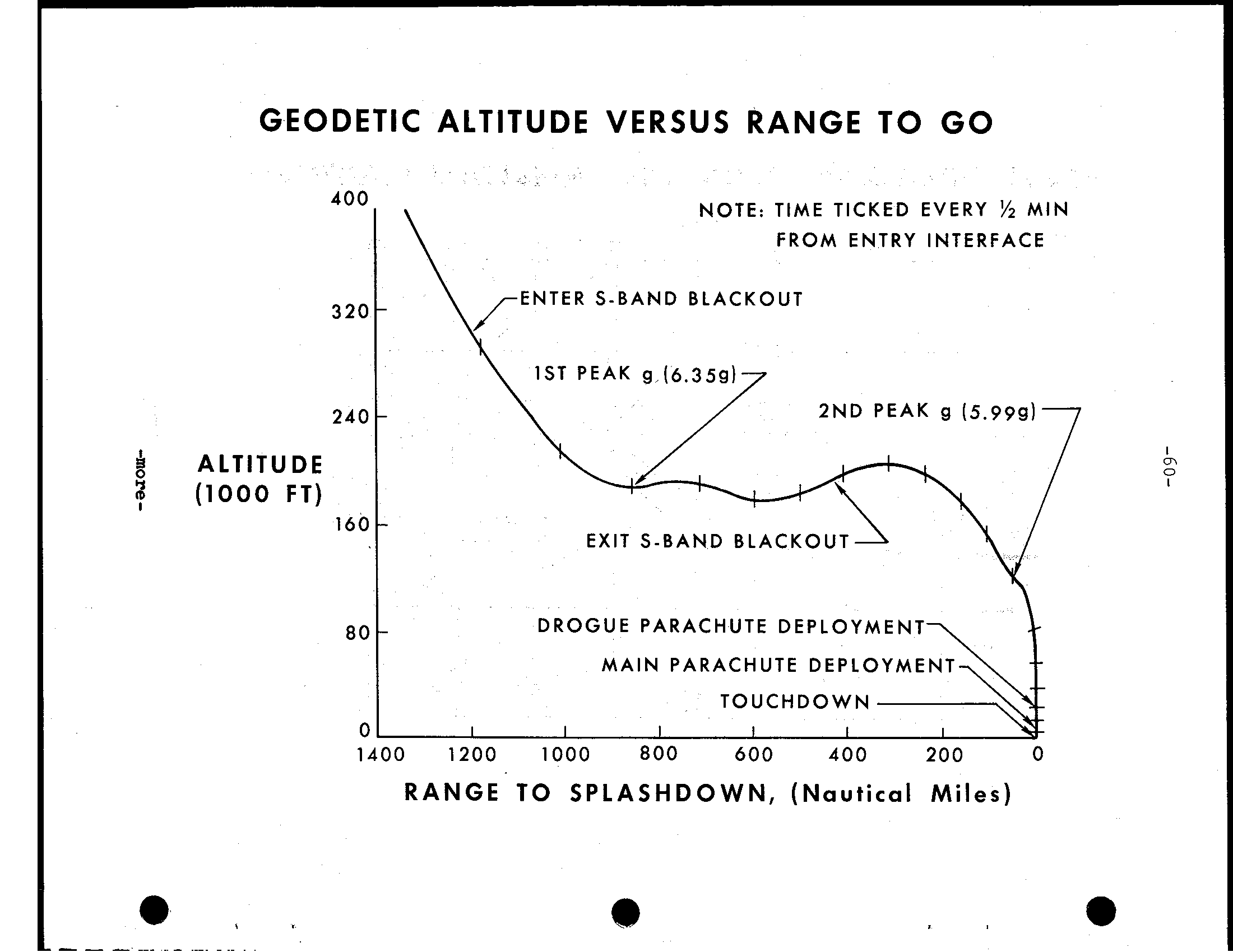
GEODETIC ALTITUDE VERSUS RANGE TO GO 400 NOTE: TIME TICKED EVERY '/2 MIN FROM E N T R Y INTERFACE ENTER S-BAND BLACKOUT 320 1ST PEAK g (6.359 240 2ND PEAK g (5.9991 ALTITUDE FT) 160 E X I T S-BAND BLACK0 80 DROGUE PARACHUTE DEPLOYMENT M A I N PARACHUTE DEPLOYMENT TOUCH D O W N 0 1400 1200 1000 800 600 4 0 0 200 0 RANGE TO SPLASHDOWN, (Nautical Miles)
c 0' N N m O 0 E W LANDING AREA
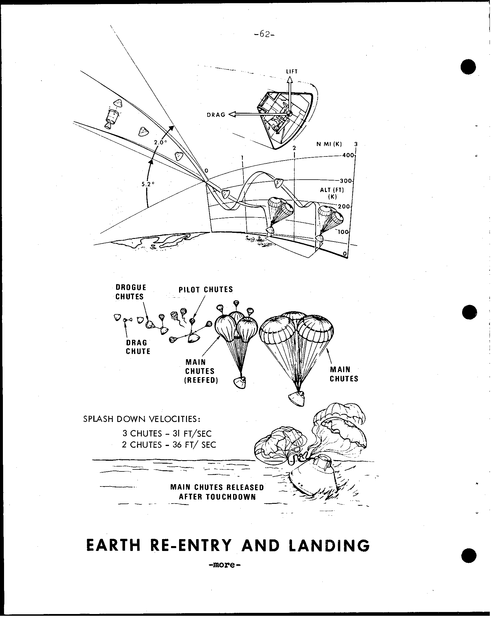
i I m LIFT DROGUE PILOT CHUTES CHUTES DRAG CHUTE N TES SPLASH DOWN VELOCITIES: - 3 CHUTES 31 FT/SEC - 2 CHUTES 36 FT/ SEC M A I N CHUTES RELEASED AFTER T O U C H D O W N -_ - _ _ -~ ~ ~~ EARTH RE-ENTRY AND LAN - -more
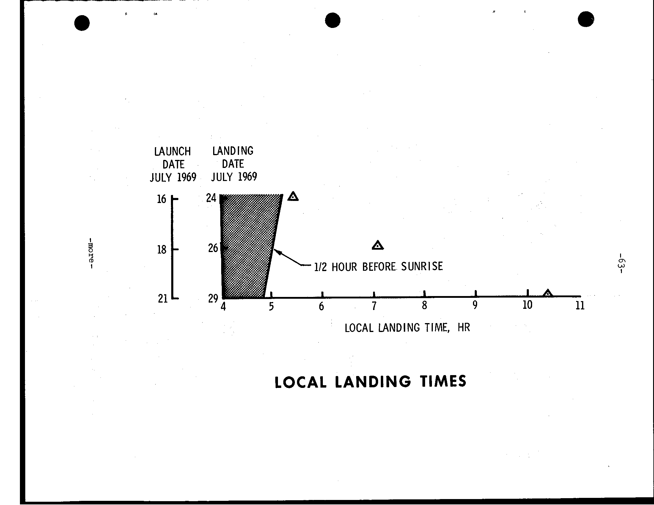
LAUNCH LANDING DATE DATE JULY 1969 JULY 1969 A HOUR BEFORE SUNRISE I J I I I h 5 6 7 8 9 10 11 LOCAL LANDING TIME, HR LOCAL LANDING TIMES
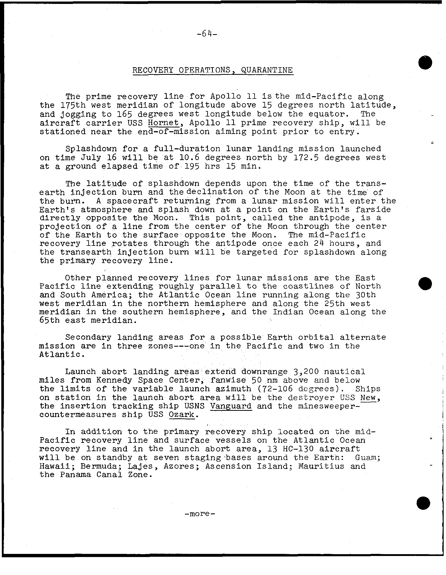
-64- RECOVERY OPERATIONS, QUARANTINE The prime recovery l i n e f o r Apollo the mid-Pacific along the 175th west meridian of longitude above 15 degrees north l a t i t u d e, and jogging t o 165 degrees west longitude below the equator. The a i r c r a f t c a r r i e r USS Hornet, Apollo prime recovery s h i p, w i l l be stationed near the end-of-mission aiming point p r i o r t o entry. - Splashdown f o r full-duration lunar landing mission launched on time July 16 w i l l 10.6 degrees north by 172.5 degrees west ground elapsed t i m e of 195 hrs 15 min. The l a t i t u d e of splashdown depends upon the time of the trans- e a r t h i n j e c t i o n burn and thedeclination of t h e Moon the time of burn. A spacecraft returning from lunar mission w i l l e n t e r t h e Eart h's atmosphere and splash down point on E a r t h's farside d i r e c t l y opposite the Moon. T h i s point, called the antipode, projection of l i n e from the center of the Moon through the center of E a r t h t o surface opposite the Moon. mid-Pacific recovery l i n e r o t a t e s through antipode once each 24 hours, and transearth i n j e c t i o n burn w i l l be targeted f o r splashdown along the primary recovery l i n e. Other planned recovery l i n e s f o r lunar missions are t h e E a s t Pacific l i n e extending roughly p a r a l l e l t o the coastlines North and South America; the Atlantic Ocean l i n e running along the 30th west meridian i n the northern hemisphere and along the 25th meridian i n the southern hemisphere, and the Indian Ocean along the 65th meridian. Secondary landing f o r possible E a r t h o r b i t a l a l t e r n a t e mission i n three zones---one i n t h e Pacific and two i n the Atlantic. Launch abort landing extend downrange 3,200 nautical miles from Kennedy Space Center, fanwise 50 nm above and below l i m i t s of the variable launch azimuth (72-106 d c p e e s). Ships on s t a t i o n i n launch abort w i l l be the destroyer CSS i n s e r t i o n tracking ship USNS Vanguard minesweeper- countermeasures ship USS Ozark. I n addition t o the primary recovery ship located on the m i d - Pacific recovery l i n e and surface on the Atlantic Ocean recovery l i n e and i n the launch abort area, 13 HC-130 a i r c r a f t w i l l be on standby seven staging bases around r;he Eartn: Guam; H a w a i i; Bermuda; Azores; Ascension Island; Mauritius t h e Panama Canal Zone. -more-
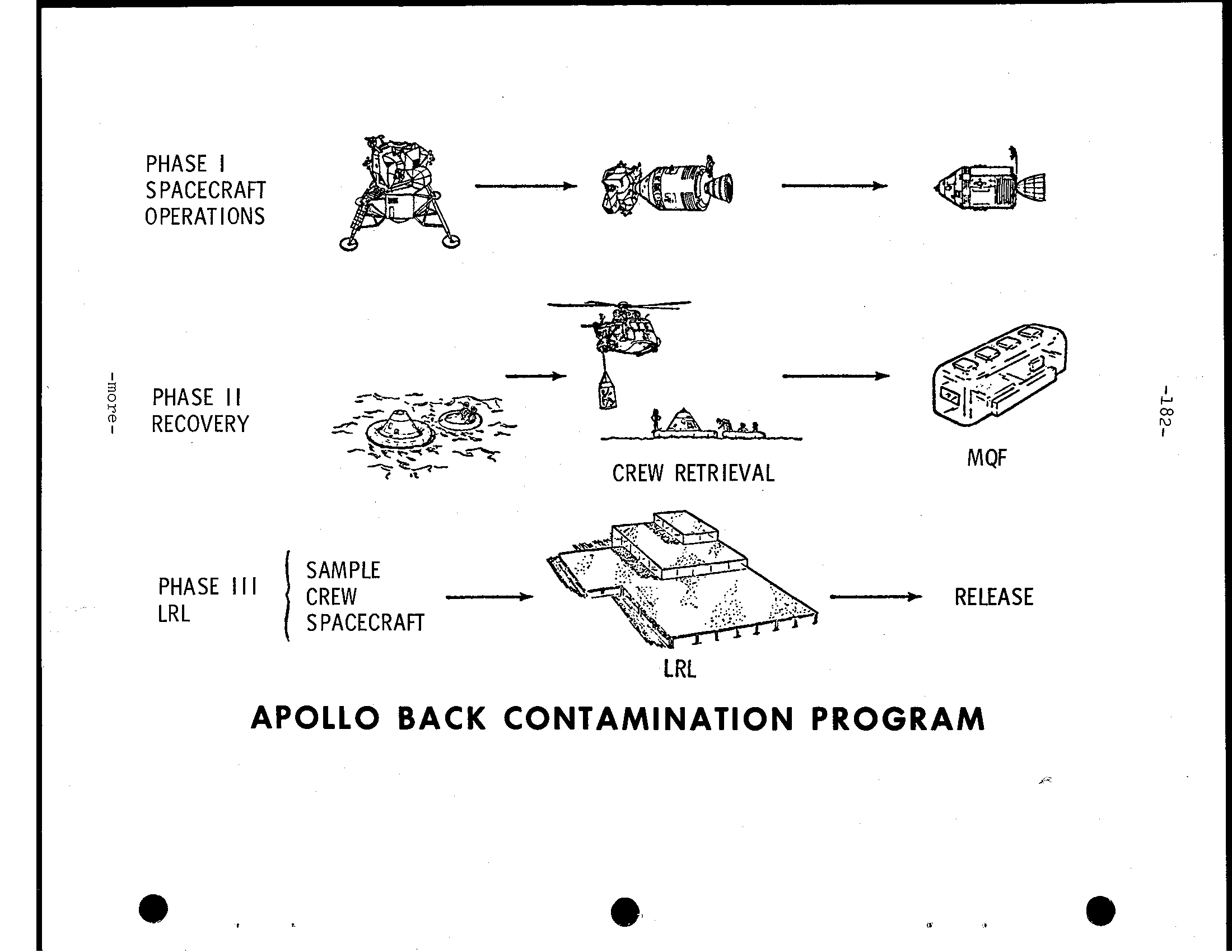
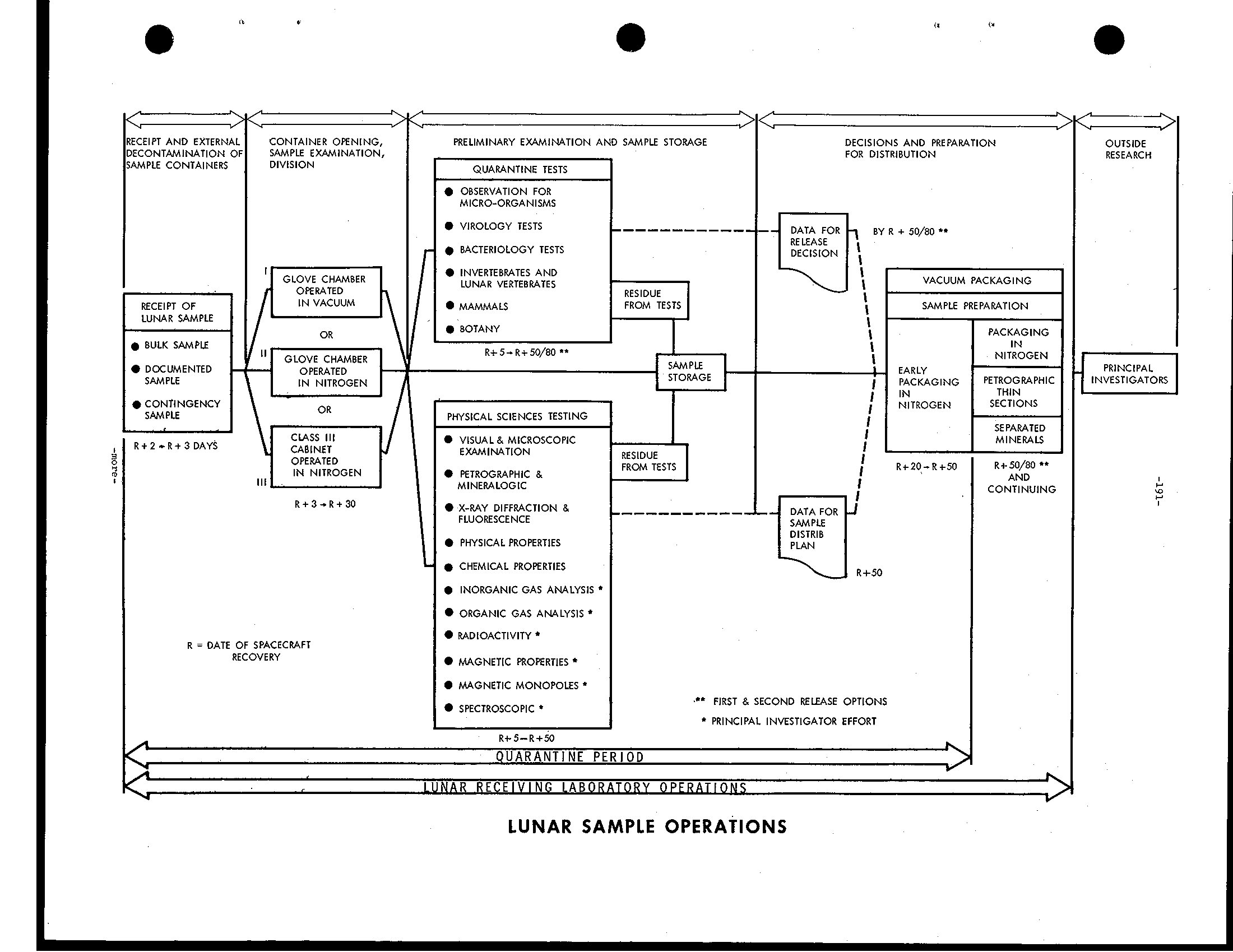
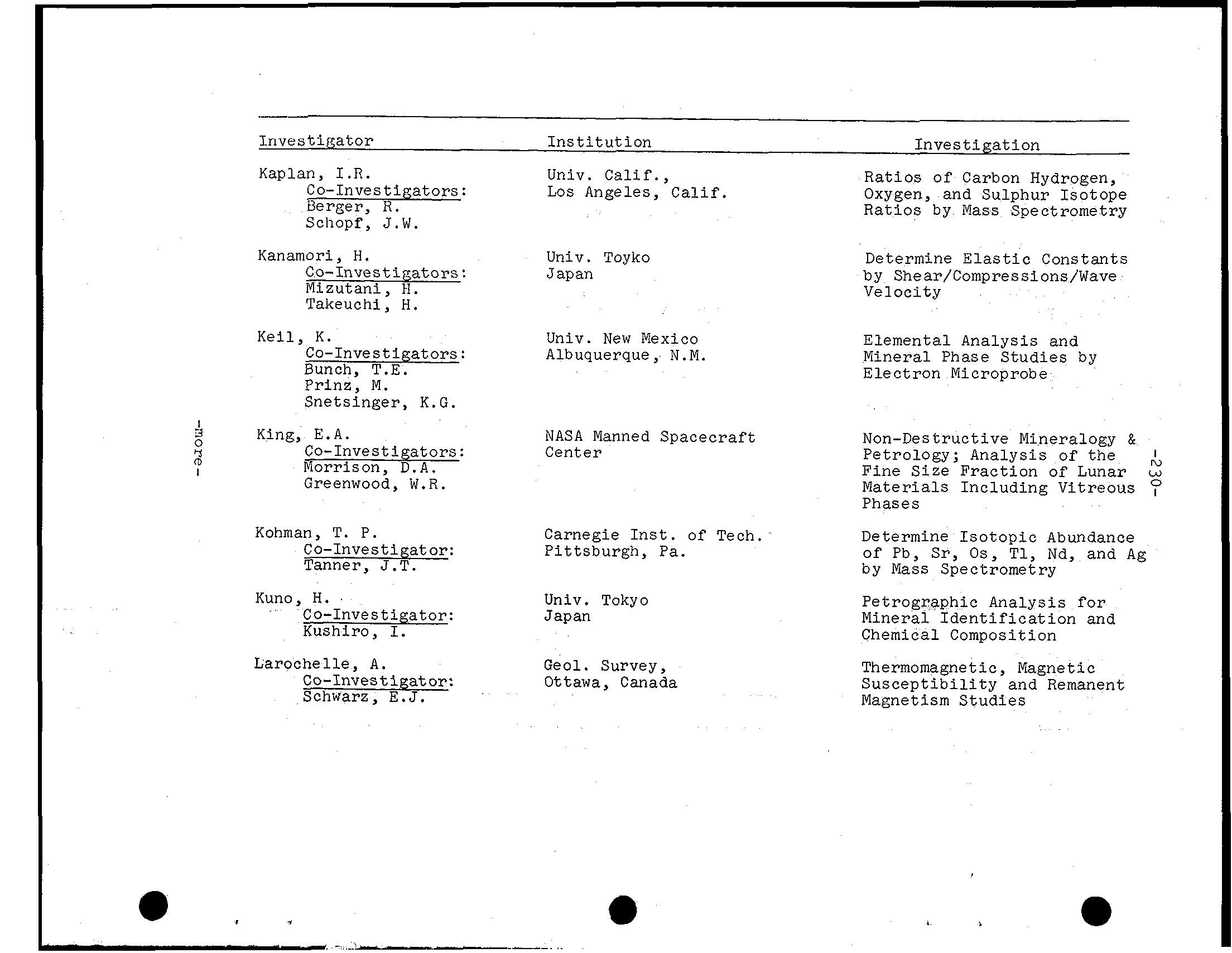
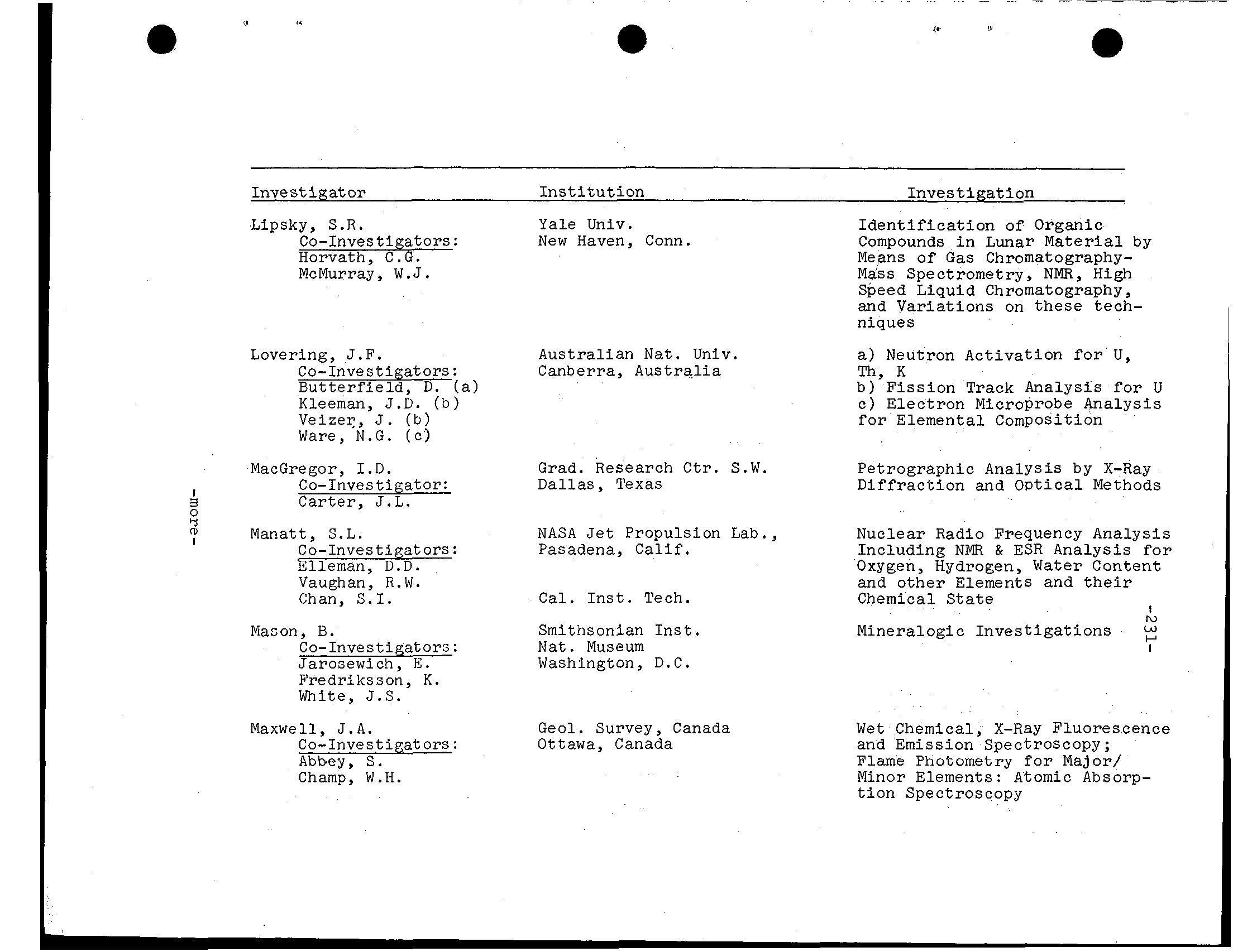
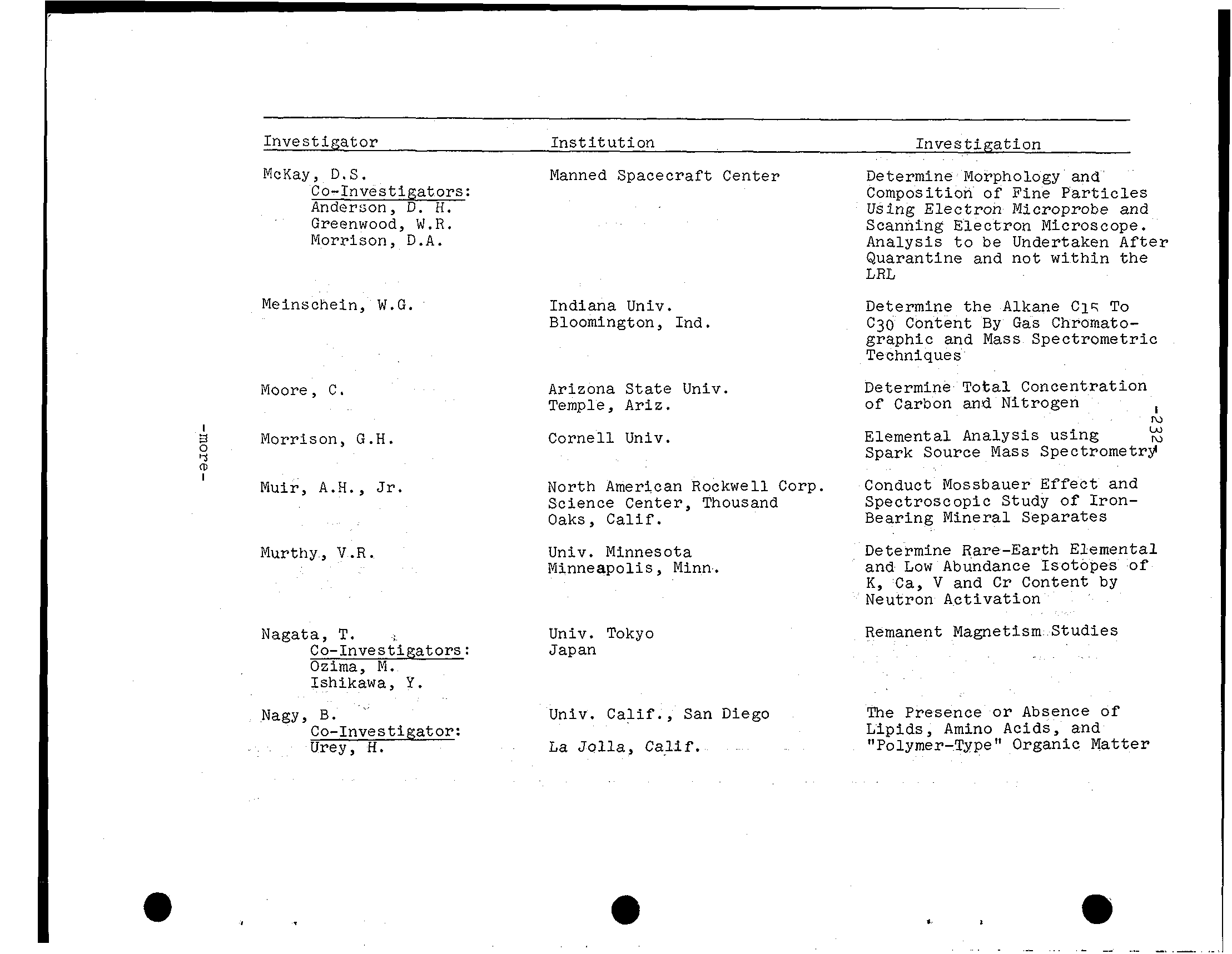
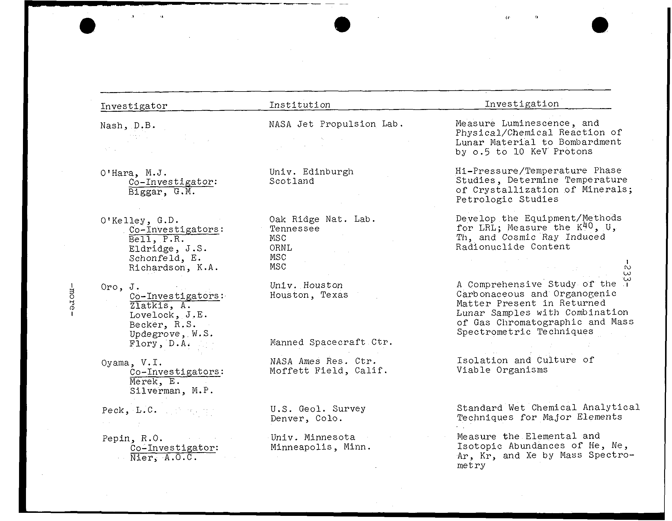
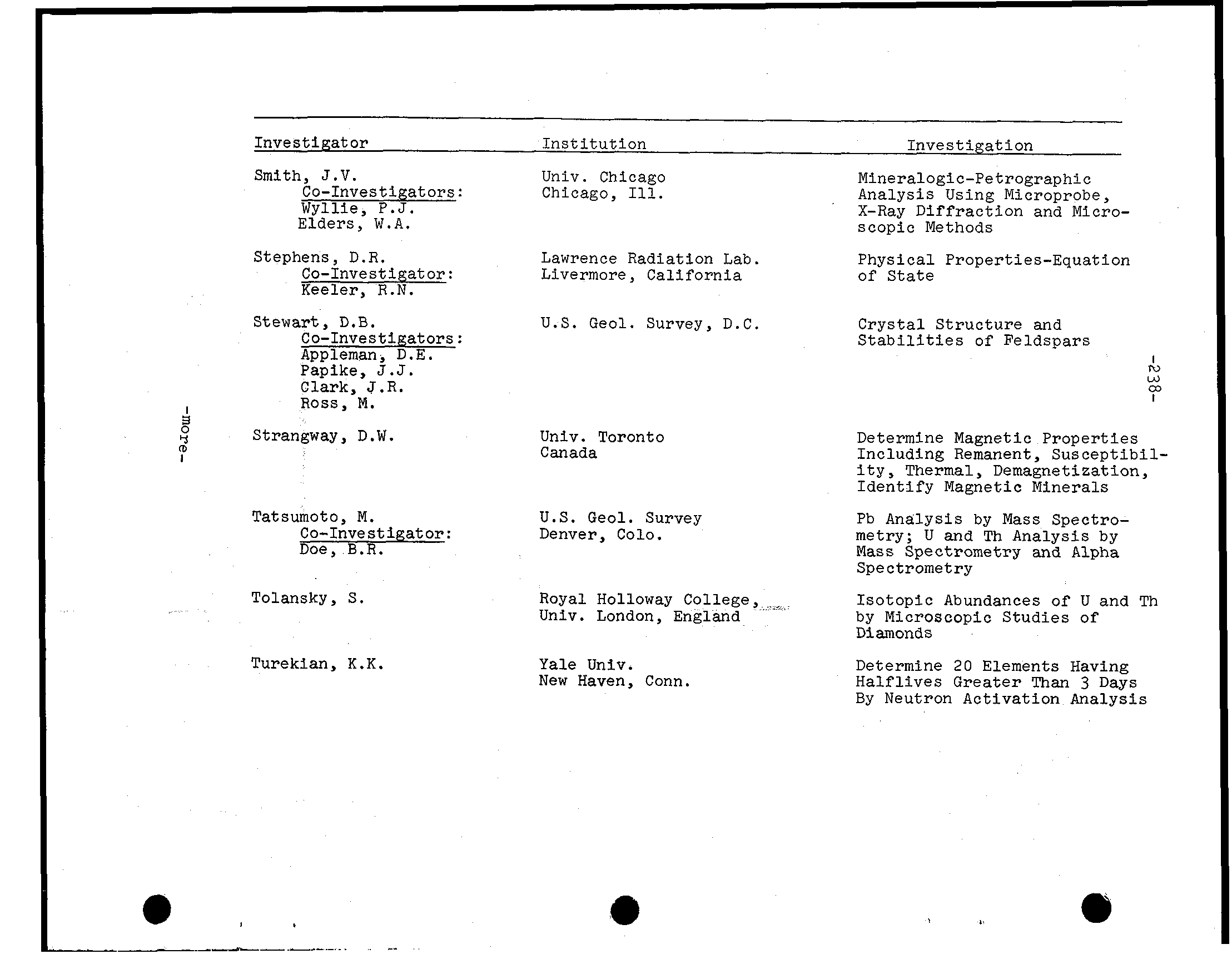
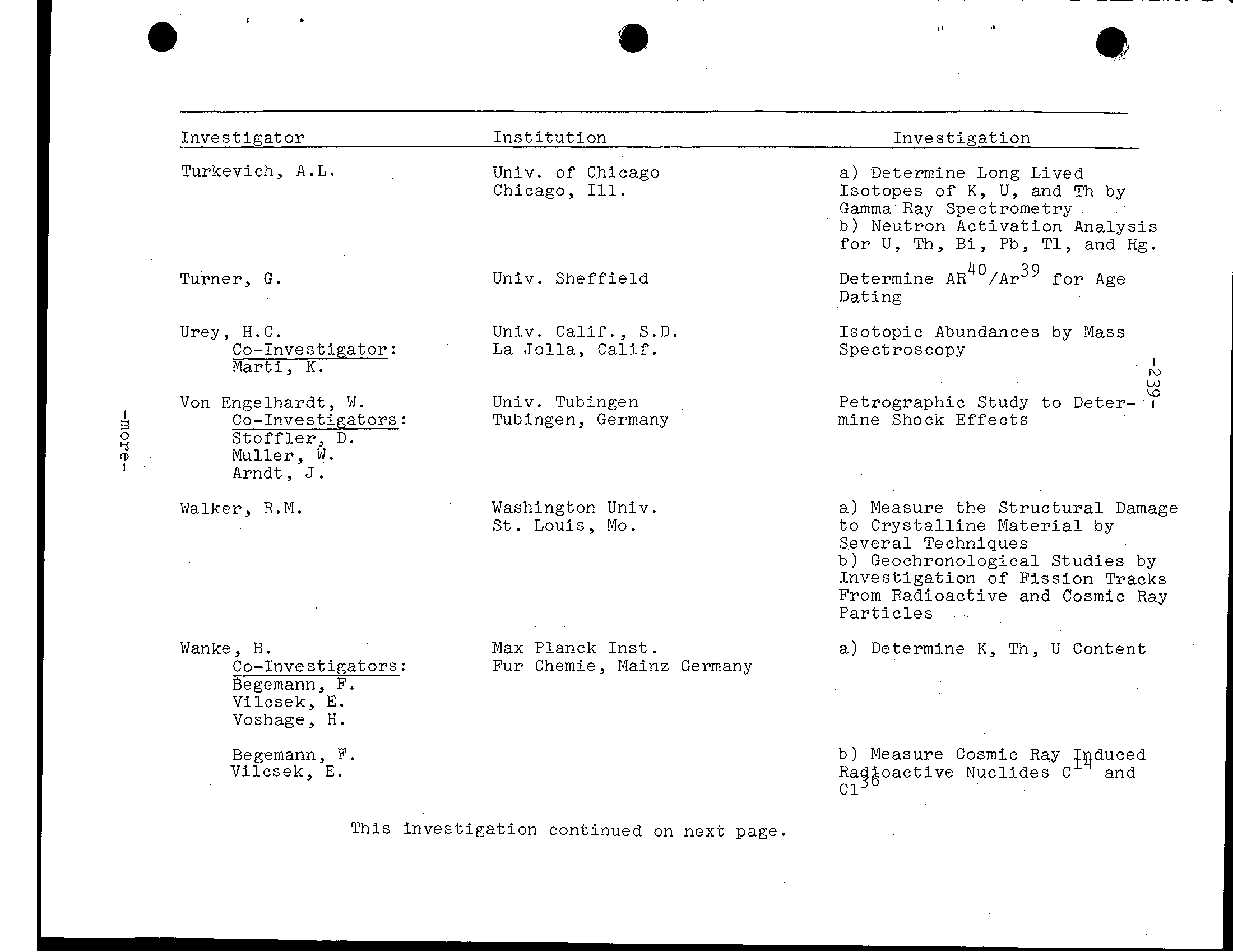
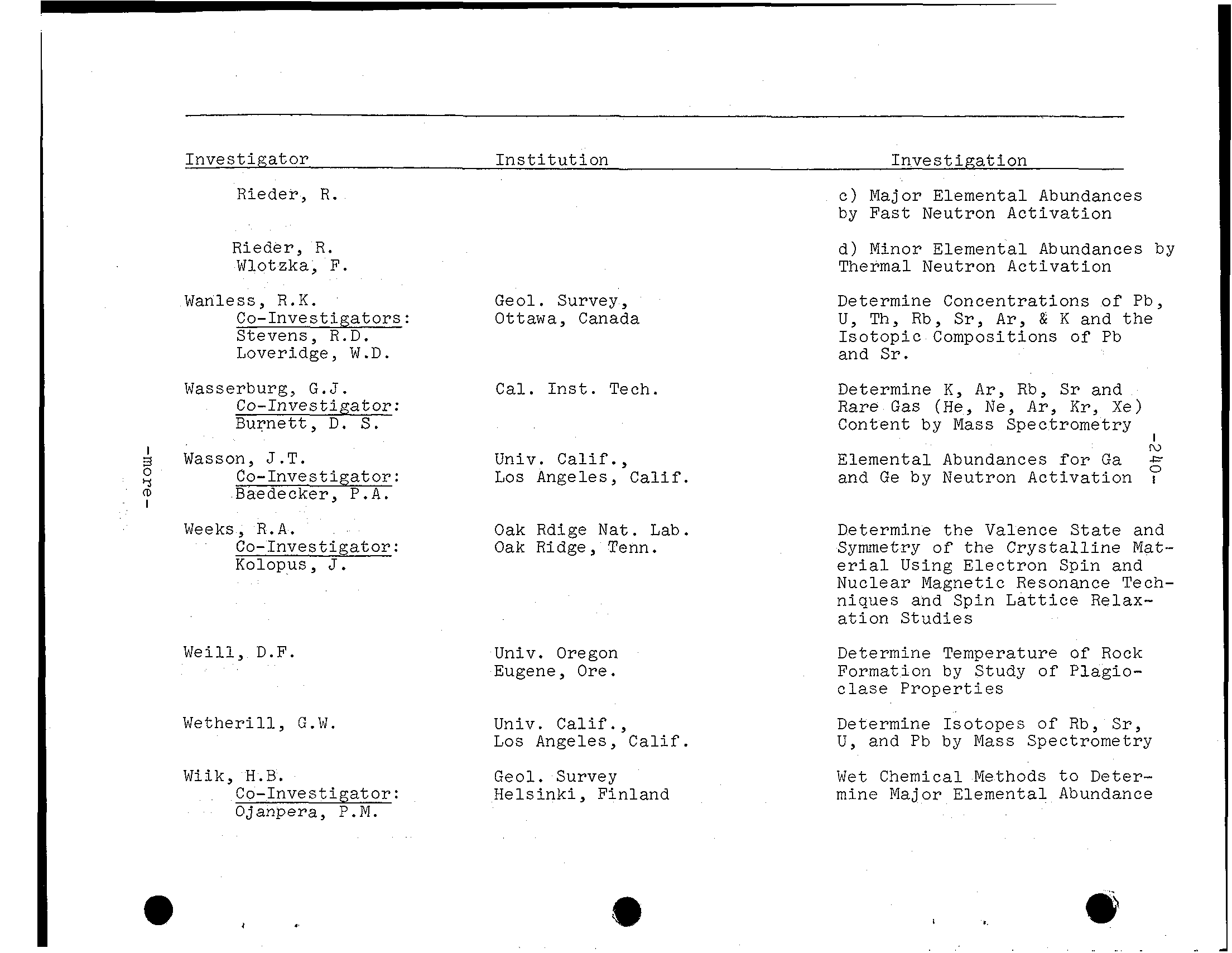
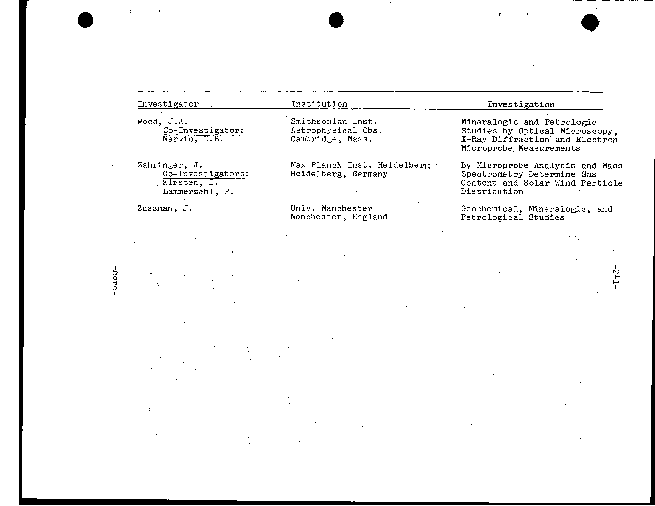
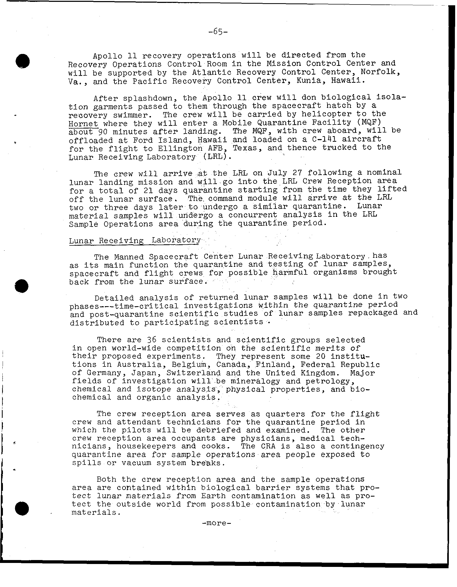
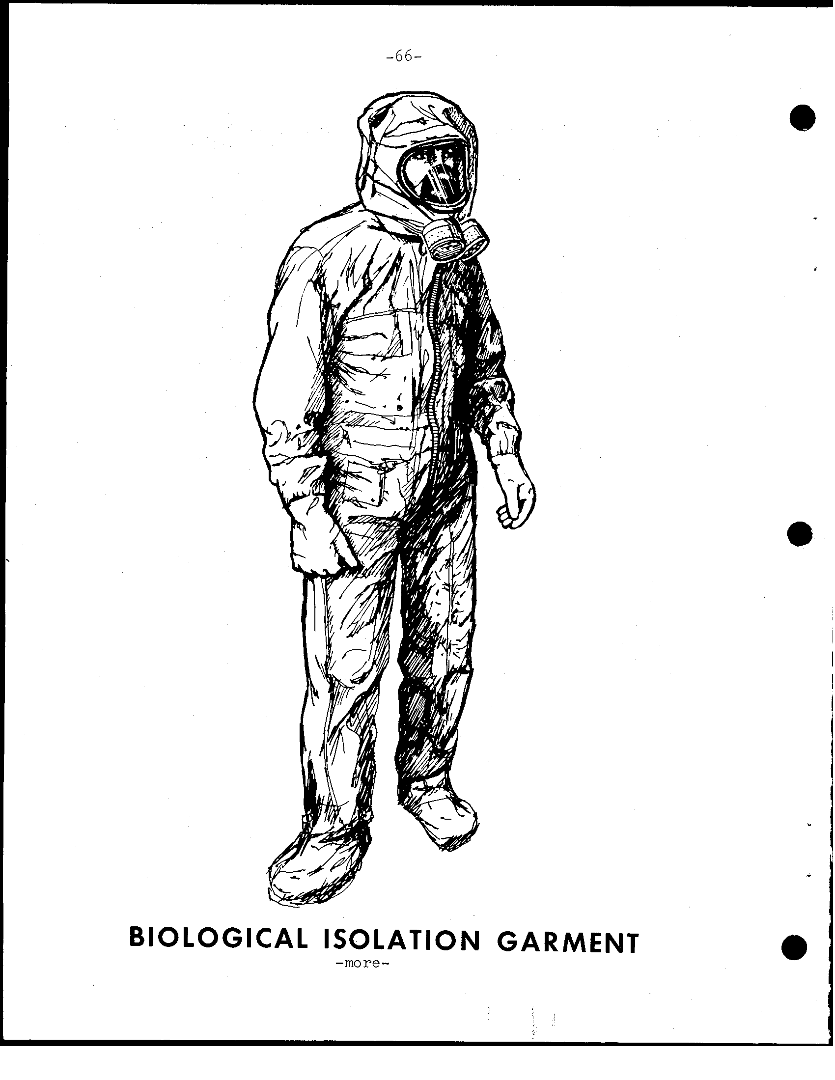
-65- Apollo recovery operations w i l l be d i r e c t e d from t h e Recovery Operations Control Room i n the Mission Control Center and w i l l be supported by t h e Atlantic Recovery Control Center, Norfolk, V a., and t h e P a c i f i c Recovery Control Center, Kunia, Hawaii. After splashdown, the Apollo crew w i l l don b i o l o g i c a l i s o l a - t i o n garments passed t o them through spacecraft hatch by recovery swimmer. The crew w i l l be c a r r i e d by h e l i c o p t e r t o Hornet where t h e y w i l l e n t e r Mobile Quarantine F a c i l i t y (MQF) about 90 minutes landing. The MQF, w i t h crew aboard, w i l l be offloaded Ford Island, Hawaii and loaded on C - 1 4 1 aircraft f o r the f l i g h t t o Ellington AFB, Texas, and thence trucked t o the Lunar Receiving Laboratory (LRL). crew w i l l arrive t h e LRL on July 27 following a nominal lunar landing mission and w i l l go i n t o LRZ, C r e w Reception f o r a t o t a l of 2 1 days quarantine s t a r t i n g from t h e time they l i f t e d o f f t h e lunar surface. The command module w i l l arrive t h e LRL two o r t h r e e days later t o undergo quarantine. Lunar samples w i l l undergo concurrent analysis i n LRL Sample Operations during the quarantine period. Lunar Receiving Laboratory The Manned Spacecraft Center Lunar Receiving Laboratory main function quarantine and t e s t i n g of lunar samples, spacecraft and f l i g h t crews possible harmful organisms brought e back from l u n a r surface. Detailed analysis of returned l u n a r samples w i l l done i n two phases---time-critical investigations within t h e quarantine period and post-quarantine s c i e n t i f i c s t u d i e s of l u n a r samples repackaged and . d i s t r i b u t e d t o p a r t i c i p a t i n g scientists There 36 s c i e n t i s t s and scientific groups selected i n open world-wide competition on the s c i e n t i f i c of t h e i r proposed experiments. They represent some 20 i n s t i t u - t i o n s i n Australia, Belgium, Canada, Finland, Federal Republic of Germany, Japan, Switzerland and t h e United Kingdom. Major of i n v e s t i g a t i o n w i l l be mineralogy and petrology, chemical and isotope analysis, physical properties, and bio- chemical and organic analysis. The crew reception area serves as q u a r t e r s f o r t h e f l i g h t crew and attendant technicians f o r the quarantine period i n which the p i l o t s w i l l debriefed and examined. The o t h e r crew reception occupants physicians, medical tech- n i c i a n s, housekeepers and cooks. The CRA a l s o contingency quarantine area f o r sample operations area people exposed t o s p i l l s o r vacuum s y s t e m breaks. Both t h e crew reception area and the sample operations a r e a are contained within b i o l o g i c a l b a r r i e r systems t h a t pro- t e c t lunar materials from Earth contamination well as pro- t e c t t h e outside world from possible contamination by lunar materials. -more-
-66- @ BIOLOGICAL ISOLATION GARMENT -more-
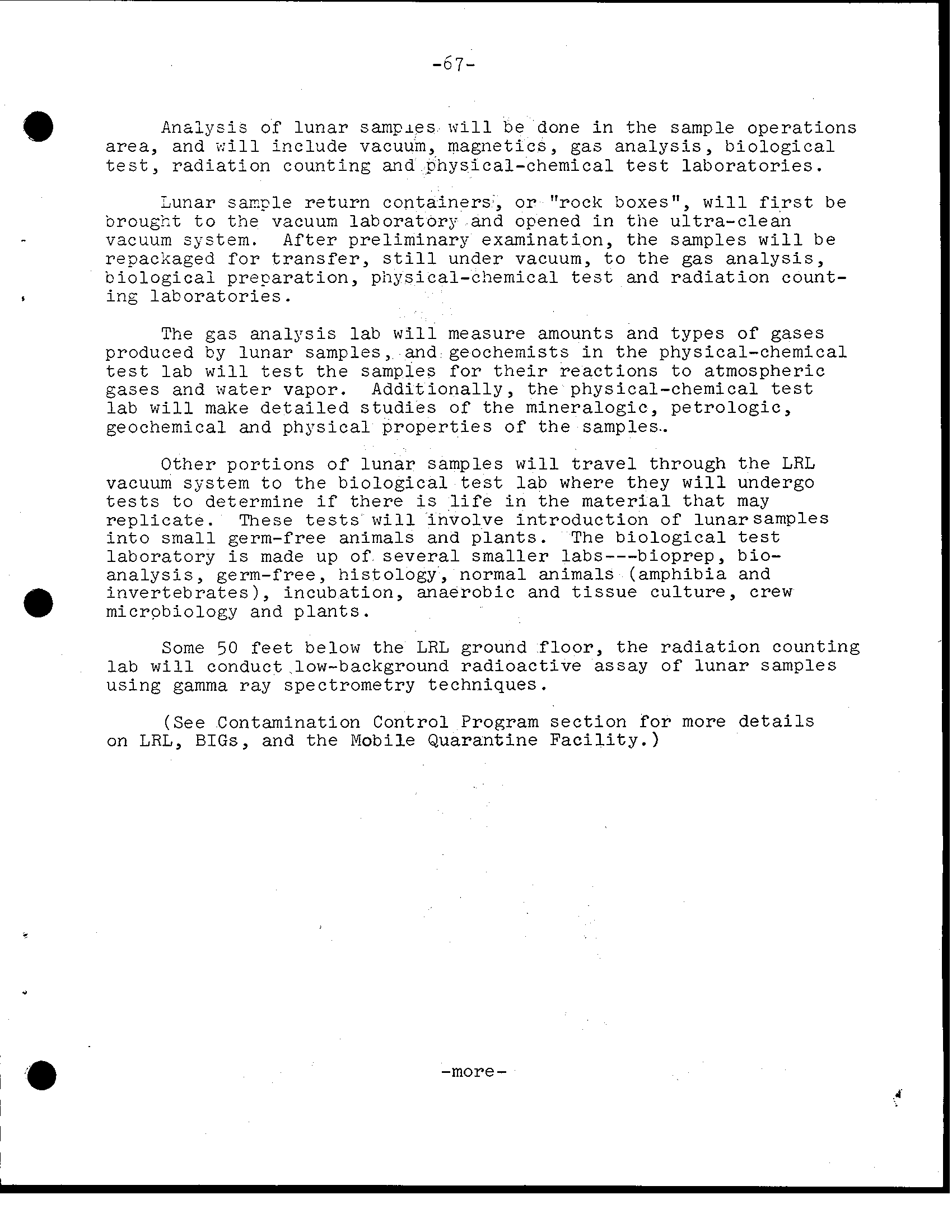
-67- a Analysis of l u n a r samples w l l l be done i n sample operations area, and x i 1 1 include vacuum, magnetics, gas a n a l y s i s, b i o l o g i c a l t e s t, r a d i a t i o n counting and physical-chemical test l a b o r a t o r i e s. Lunar saxple r e t u r n c o n t a i n e r s, or "rock boxes", w i l l be brougkt t o t h e vacuum l a b o r a t o r y and Opened i n tne u l t r a - c l e a n vacuum s~ stem. After preliminary examination, samples w i l l b e repacxaged for t r a n s f e r, under vacuum, t o a n a l y s i s, b i o l o g i c a l preparation, physical-chemical test r a d i a t i o n count- i n g l a b o r a t o r i e s. The a n a l y s i s l a b w i l l measure amounts and types of gases produced by l u n a r samples, and geochemists i n the physical-chemical t e s t l a b w i l l t h e samples for r e a c t i o n s t o atmospheric gases and water vapor. Additionally, physical-chemical l a b w i l l make s t u d i e s of mineralogic, p e t r o l o g i c, geochemical and physical p r o p e r t i e s of the samples. Other p o r t i o n s of l u n a r samples w i l l t r a v e l through LRL vacuum s y s t e m t o t h e b i o l o g i c a l test l a b where they w i l l undergo t o determine i n material may r e p l i c a t e. These t e s t s w i l l involve i n t r o d u c t i o n of lunarsamples i n t o germ-free animals and p l a n t s. The b i o l o g i c a l l a b o r a t o r y made up of s e v e r a l smaller labs---bioprep, bio- a n a l y s i s, germ-free, h i s t o l o g y, normal (amphibia and i n v e r t e b r a t e s), incubation, anaerobic and t i s s u e c u l t u r e, crew microbiology and p l a n t s. Some 50 below LRL ground f l o o r, r a d i a t i o n counting l a b w i l l conduct low-background r a d i o a c t i v e of l u n a r samples using gamma ray spectrometry techniques. (See Contamination Control Program s e c t i o n f o r more d e t a i l s on LRL, BIGS, and Quarantine F a c i l i t y.) -more- ?
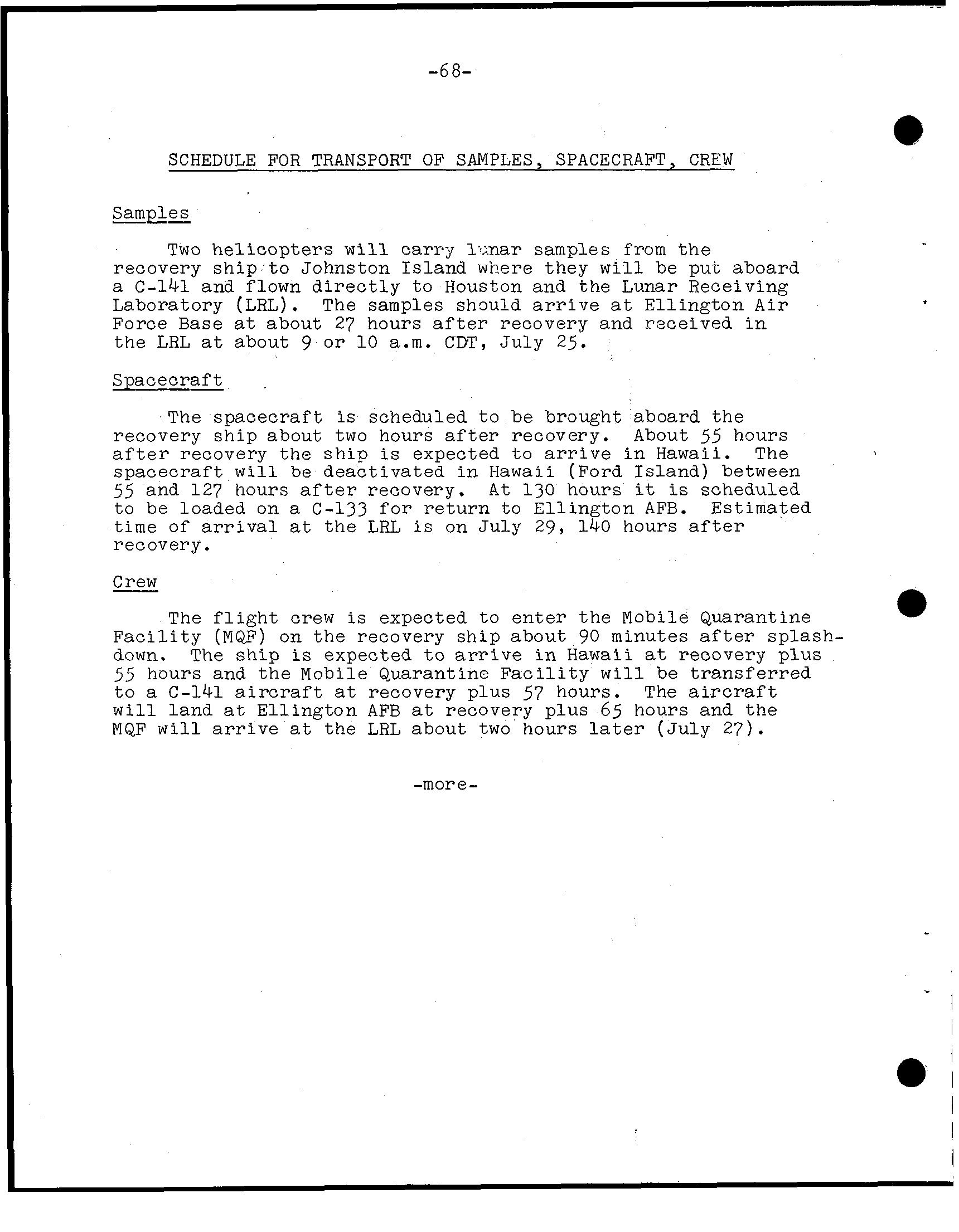
-68- SCHEDULE FOR TRANSPORT OF SAMPLES, SPACECRAFT, CREW Samples Two helicopters w i l l carry samples from t h e recovery ship t o Johnston Island where they w i l l be pu-c aboard C - 1 4 1 and flown d i r e c t l y t o Houston and the Lunar Receiving Laboratory (LRL). The samples s h m l d arrive Ellington A i r Force Base about 27 hours a f t e r recovery and received the LRL about 9 o r 10 a. m. CDT, July 25. Spacecraft The spacecraft scheduled t o be brought aboard the recovery ship about two hours a f t e r recovery. About 55 hours a f t e r recovery the s h i p expected t o a r r i v e in H a w a i i. The spacecraft w i l l deactivated i n H a w a i i (Ford between 55 and 127 hours a f t e r recovery. A t l3O hours scheduled to be loaded on C-133 f o r return to Ellington AFB. Estimated time of a r r i v a l the LRL July 29, 140 hours recovery. Crew The f l i g h t crew expected t o enter the Mobile Quarantine F a c i l i t y (MQF) on the recovery ship about 90 minutes a f t e r splash- down. The ship expected t o arrive H a w a i i recovery plus 55 hours and t h e Mobile Quarantine F a c i l i t y w i l l be transferred t o C - 1 4 1 recovery plus 57 hours. The w i l l land Ellington AFB recovery plus 65 hours and MQF w i l l a r r i v e the LRL about two hours l a t e r (July 27). - -more
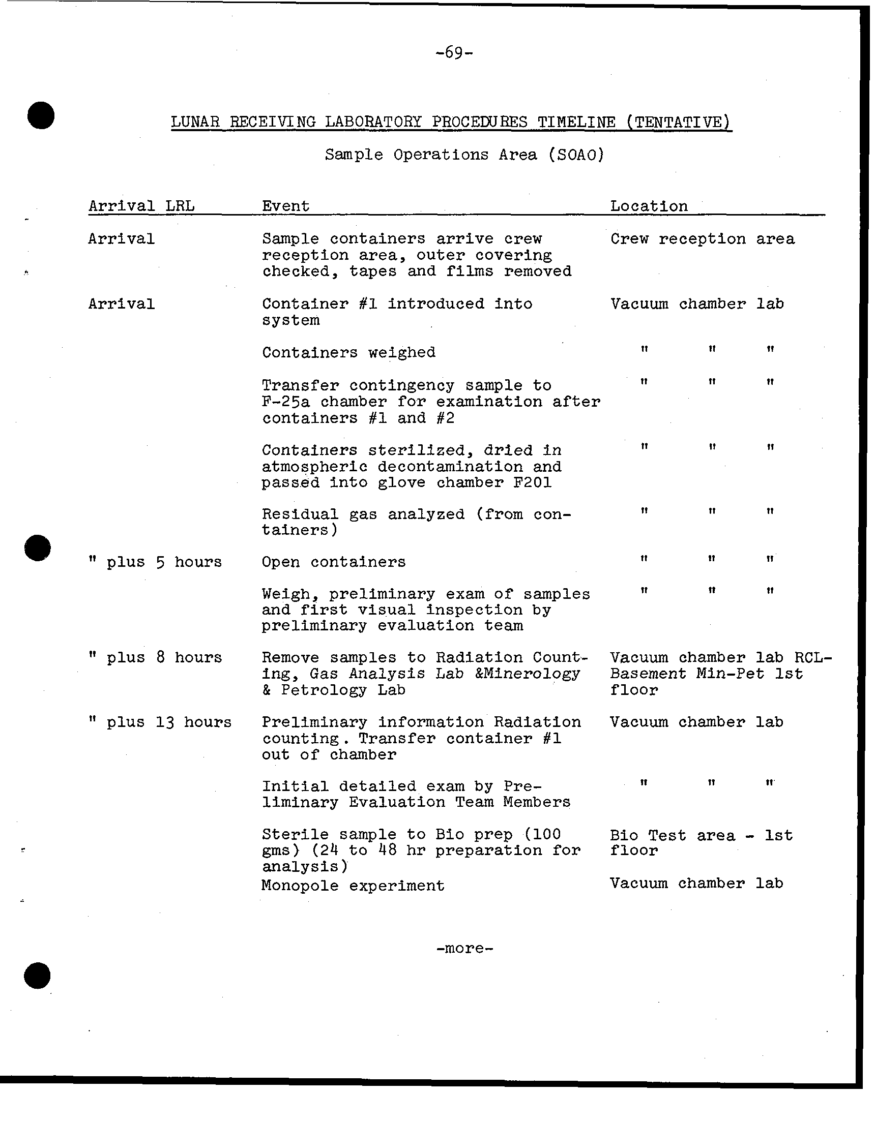
-69- LUNAR RECEIVING LABORATORY PROCEWRES TIMELINE (TENTATIVE) Sample Operations Area (SOAO) Arrival LRL Event Location Arrival Sample containers arrive crew C r e w reception area reception area, outer covering checked, tapes and removed Arrival Container introduced i n t o Vacuum chamber system Containers weighed 11 It 11 Transfer contingency sample t o 11 11 It F-25a chamber f o r examination a f t e r containers and #2 Containers sterilized, dried i n 11 I1 atmospheric decontamination and passed i n t o glove chamber F201 Residual gas analyzed (from con- I1 11 11 tainers) plus 5 hours Open containers 11 I1 11 Weigh, preliminary exam of samples 11 11 It and visual inspection by preliminary evaluation plus 8 hours Remove samples t o Radiation Count- Vacuum chamber RCL- ing, Gas Analysis Lab &Minerology Basement Min-Pet & Petrology Lab floor plus 13 hours Preliminary information Radiation Vacuum chamber counting. Transfer container out of chamber I n i t i a l detailed exam by Pre- 11 11 11 liminary Evaluation Team Members - S t e r i l e sample t o Bio prep (100 Bio Test area g m s) (24 t o 48 hr preparation f o r floor analysis) Monopole experiment Vacuum chamber * -more-
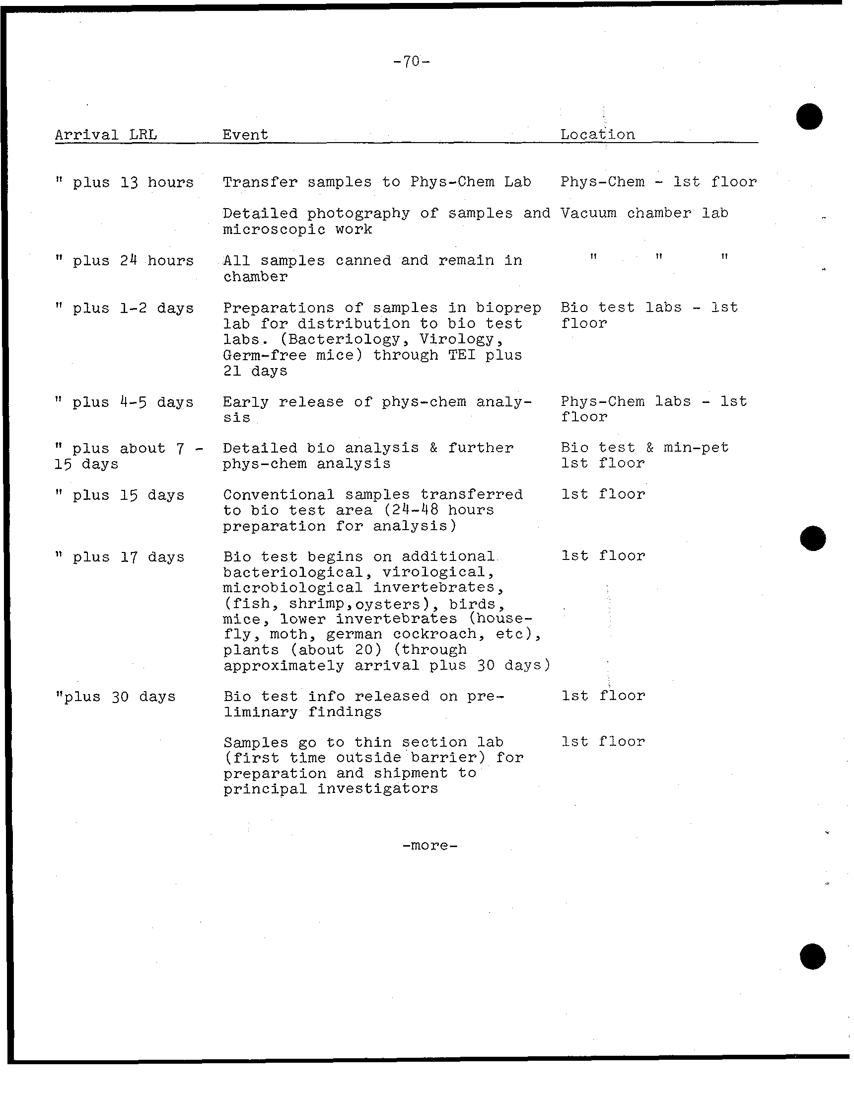
-70- Arrival LRL Event Locat ion - plus 13 hours Transfer samples to Phys-Chem Lab Phys-Chem 1st floor It Detailed photography of samples and Vacuum chamber lab microscopic work plus 24 hours All samples canned and remain in 11 1, 11 chamber plus 1-2 days Preparations of samples in bioprep Bio test labs 1st lab for distribution to bio test floor labs. (Bacteriology, Virology, Germ-free mice) through TEI plus 21 days plus 4-5 days Early release of phys-chem analy- Phys-Chem labs 1st sis floor - plus about 7 Detailed bio analysis & further Bio test & min-pet 15 days phys-chem analysis 1st floor plus 1 5 days Conventional samples transferred 1st floor I t to bio test area (24-48 hours preparation for analysis) plus 17 days Bio test begins on additional 1st floor bacteriological, virological, microbiological invertebrates, (fish, shrimp,ogsters), birds, mice, lower invertebrates (house- fly, moth, german cockroach, etc), plants (about 20) (through approximately arrival plus 30 days) "plus 30 days Bio test info released on pre- 1st floor liminary findings Samples go to thin section lab 1st floor (first time outside barrier) for preparation and shipment to principal investigators -more-
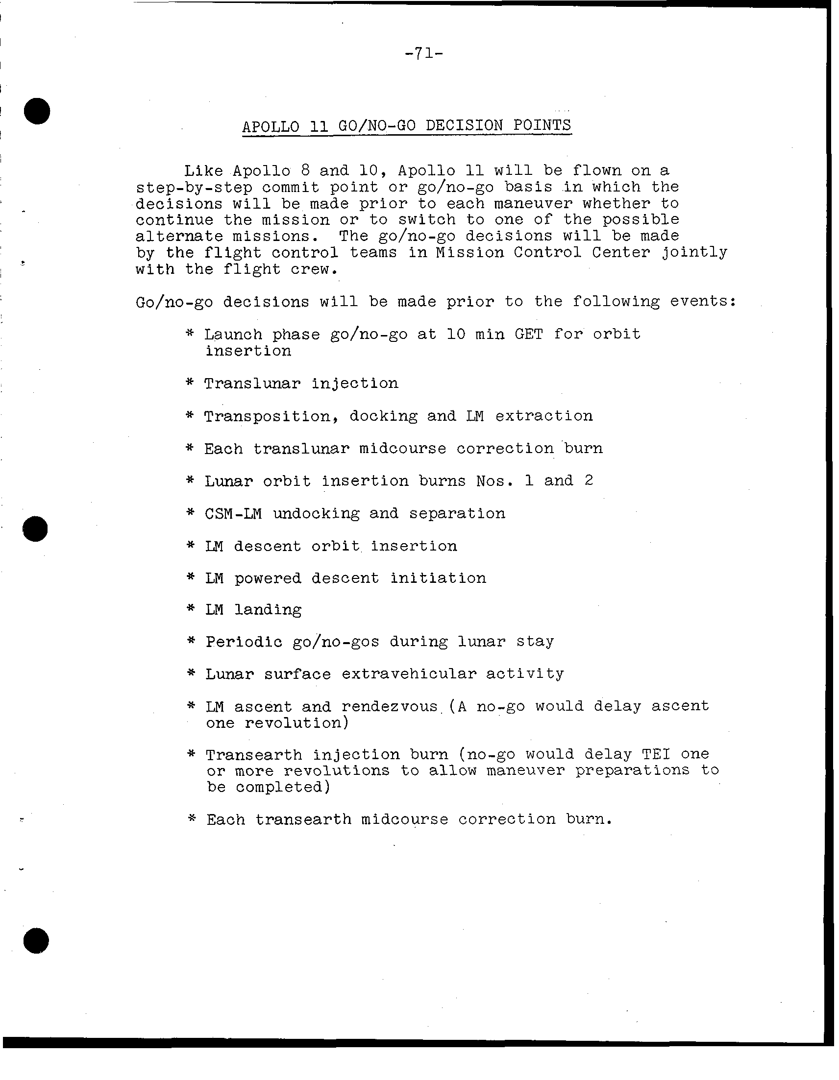
-71- APOLLO 11 GO/NO-GO DECISION POINTS Like Apollo 8 and 10, Apollo 11 will be flown on a step-by-step commit point or go/no-go basis in which the decisions will be made prior to each maneuver whether to continue the mission or to switch to one of the possible alternate missions. The go/no-go decisions will be made by the flight control teams in Mission Control Center jointly with the flight crew. Go/no-go decisions will be made prior to the following events: * Launch phase go/no-go at min GET for orbit insertion * Translunar injection * Transposition, docking and LM extraction * Each translunar midcourse correction burn * Lunar orbit insertion burns Nos. 1 and 2 * CSM-LM undocking and separation * LM descent orbit insertion * LM powered descent initiation * LM landing * Periodic go/no-gos during lunar stay * Lunar surface extravehicular activity * LM ascent and rendezvous (A no-go would delay ascent one revolution) * Transearth injection burn (no-go would delay TEI one or more revolutions to allow maneuver preparations to be completed) * Each transearth midcourse correction burn.
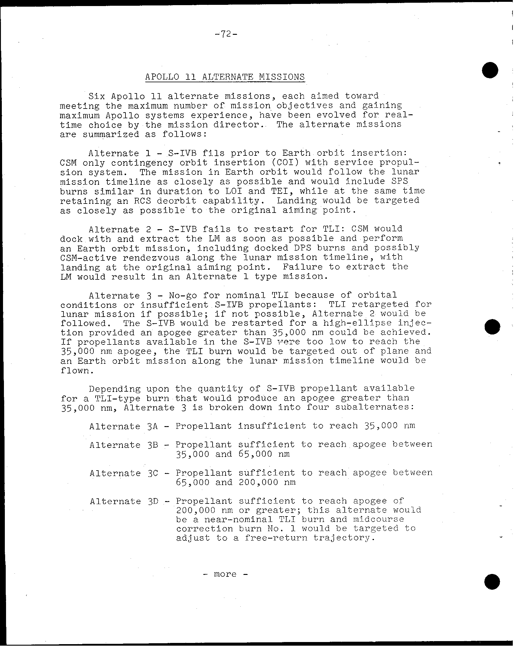
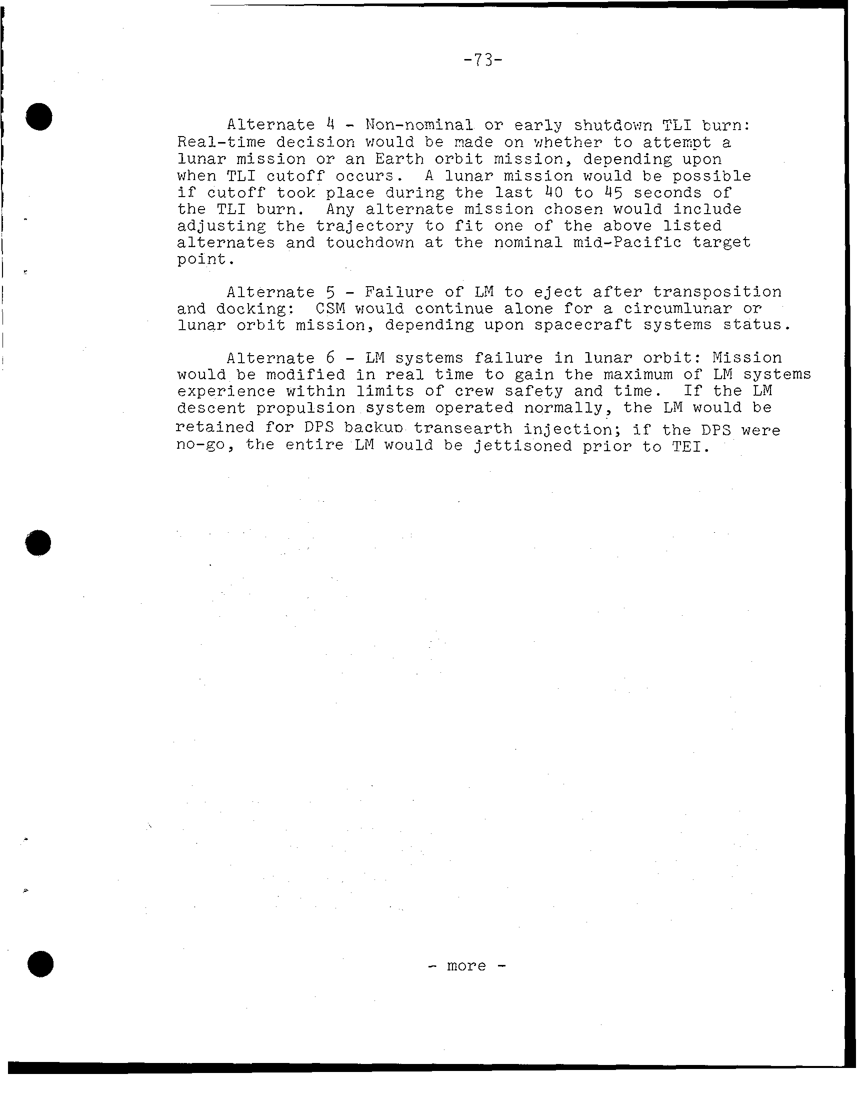
- 7 2 - APOLLO 11 ALTERNATE MISSIONS Six Apollo 11 alternate missions, each aimed toward meeting the maximum number of mission objectives and gaining maximum Apollo systems experience, have been evolved for real- time choice by the mission director. The alternate missions are summarized as follows: Alternate 1 S-IVB fils prior to Earth orbit insertion: CSM only contingency orbit insertion (COI) with service propul- sion system. The mission in Earth orbit would follow the lunar mission timeline as closely as possible and would include SPS burns similar in duration to LO1 and TEI, while at the same time retaining an RCS deorbit capability. Landing would be targeted as closely as possible to the original aiming point. - Alternate 2 S-IVB fails to restart for TLI: CSM would dock with and extract the LM as soon as possible and perform an Earth orbit mission, including docked DPS burns and possibly CSM-active rendezvous along the lunar mission timeline, with landing at the original aiming point. Failure to extract the LM would result in an Alternate type mission. Alternate 3 No-go for nominal TLI because of orbital conditions or insufficient S-IYB propellants: TLI retargeted for lunar mission if possible; if not possible, Alternake 2 would be followed. The S-IVB would be restarted for a high-ellipse injec- tion provided an apogee greater than 35,000 nm could be achieved. If propellants available in the S-IVB','e?e too low to reach the 35,000 nm apogee, the TLI burn would be targeted out of plane and an Earth orbit mission along the lunar mission timeline would be . flown Depending upon the quantity of S-IVB propellant available for a TLI-type burn that would produce an apogee greater than 35,000 nm, Alternate 3 is broken down into four subalternates: Alternate 3A Propellant insufficient to reach 35,000 rim - Alternate 3B Propellant sufficient to reach apogee between 35,000 and 65,000 nm Alternate 3C Propellant sufficient to reach apogee between 65,000 and 200,000 nm Alternate 39 Propellant sufficient to reach apogee of 200,000 nm or greater; this alternate would be a near-nominal TLI burn and midcourse correction burn No. 1 would be targeted to adjust to a free-return trajectory. more -
-73- - Alternate 4 Non-nominal or early shut8o.m TLI burn: Real-time decision would be rade on whether to attempt a lunar mission or an Earth orbit mission, depending upon when TLI cutoff occurs. A lunar mission would be possible if cutoff took place during the last 40 to 45 seconds of the TLI burn. Any alternate mission chosen would include I * adjusting the trajectory to fit one of the above listed alternates and touchdown at the nominal mid-Pacific target I point. i - I Alternate 5 Failure of LM to eject after transposition and docking: CSM would continue alone f o r a circumlunar or lunar orbit mission, depending upon spacecraft systems status. Alternate 6 LM systems failure in lunar orbit: Mission would be modified in real time to gain the maximum of LM systems experience within limits of crew safety and time. the LM descent propulsion system operated normally, the LM would be retained for DPS backua transearth injection; if the DPS were no-go, the entire LM would be jettisoned prior to TEI. - more
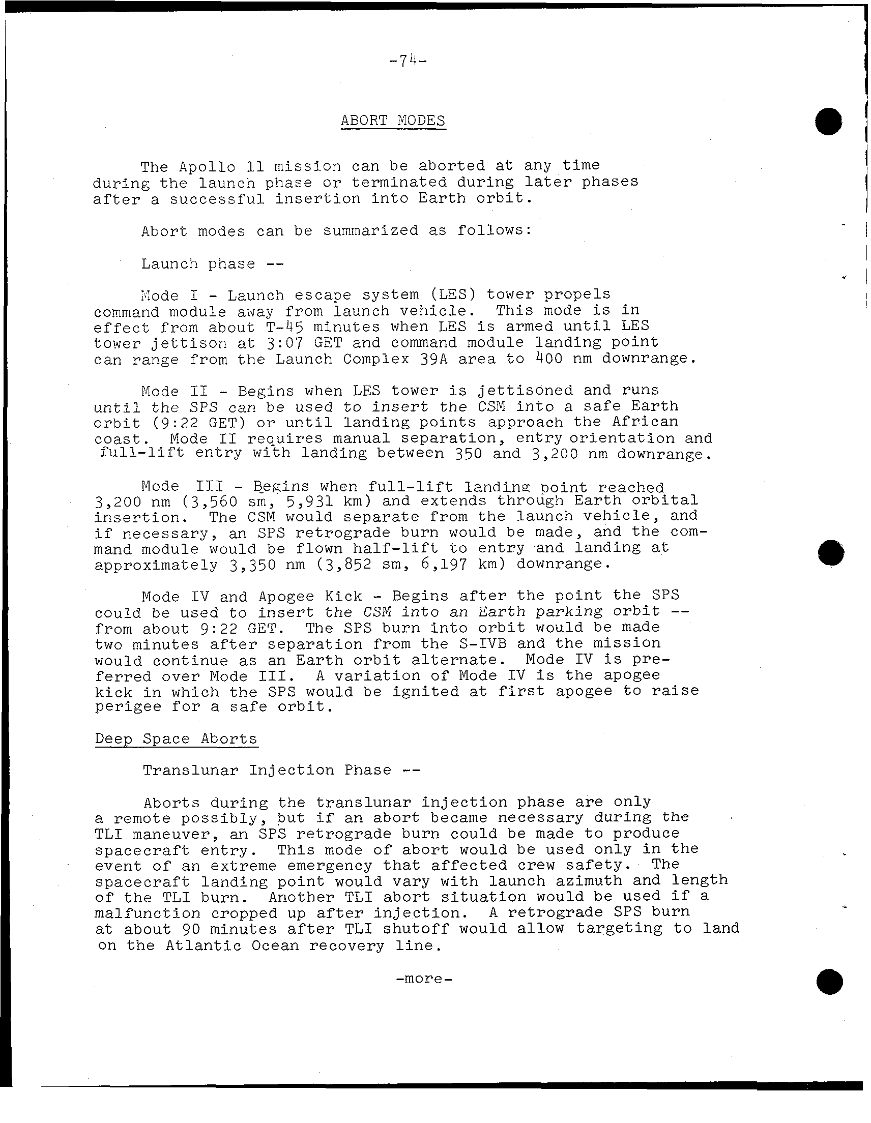
! ABORT MODES The Apollo m i s s i o n can be aborted any time during t h e launch phase or terminated during phases a f t e r a successful i n s e r t i o n i n t o Earth o r b i t. - 1 Abort m.odes can be summarized as follows: I Launch phase . I ;;ode Launch escape system (LES) tower propels command module away from launch vehicle. T h i s mode i n e f f e c t from about T-45 minutes when LES armed u n t i l LES tower j e t t i s o n 3:07 GET and command module landing point can range from t h e Launch Complex 39A area to 400 nm downrange. Mode I1 Begins when LES tower j e t t i s o n e d and runs u n t i l t h e SPS can be used to i n s e r t t h e CSM i n t o a Earth o r b i t (9: 2 2 GET) o r u n t i l landing points approach t h e African coast. Mode I1 requires manual separation, entry o r i e n t a t i o n and f u l l - l i f t entry with landing between 350 and 3,200 nm downrange. Mode I11 Begins when f u l l - l i f t l a n d i n g ~ o i n tre ached. 3,200 nm (3,560 s m, 5,931 km) and extends through E a r t h o r b i t a l i n s e r t i o n. The CSM would separate from t h e launch vehicle, and necessary, an SPS retrograde burn would be made, and t h e com- mand module would be flown t o entry and landing approximately 3,350 nm (3,852 s m, 6,197 km) downrange. - Mode I V and Apogee Kick Begins t h e point SPS could be used t o i n s e r t the CSM i n t o an E a r t h parking o r b i t from about 9: 2 2 GET. The SPS burn i n t o o r b i t would be made two minutes separation from t h e S-IVB and t h e mission would continue an E a r t h o r b i t a l t e r n a t e. Mode I V pre- f e r r e d over Mode A v a r i a t i o n o f Mode I V t h e apogee kick i n which t h e SPS would be i g n i t e d apogee to perigee for safe o r b i t. Deep Space Aborts -- Translunar I n j e c t i o n Phase Aborts during t r a n s l u n a r i n j e c t i o n phase only remote possibly, but an abort became necessary during T L I maneuver, an SPS retrograde burn could be made to produce spacecraft e n t r y. This mode of abort would be used only i n event of an extreme emergency affected crew s a f e t y. The spacecraft landing point would vary w i t h launch azimuth and length of TLI burn. Another TLI abort s i t u a t i o n would be used malfunction cropped up i n j e c t i o n. A retrograde SPS burn about 90 minutes after T L I shutoff would allow t a r g e t i n g to land on t h e A t l a n t i c Ocean recovery l i n e. -more-
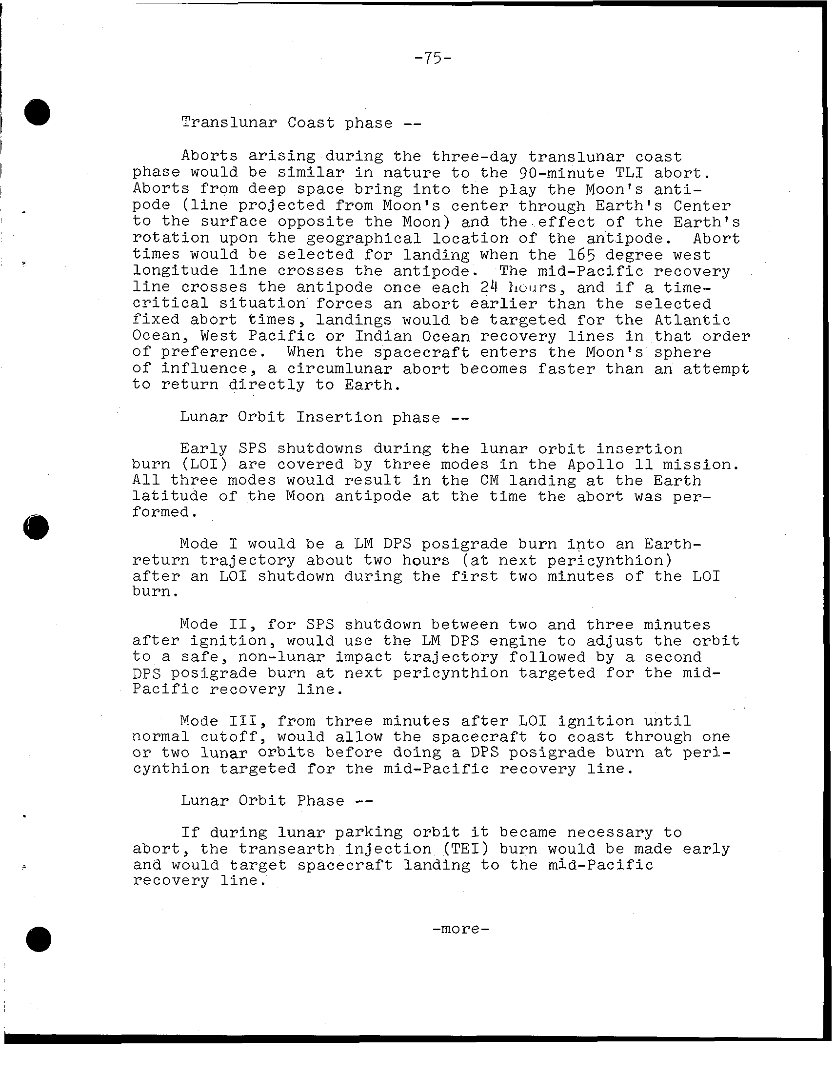
-75- Translunar Coast phase Aborts a r i s i n g during the three-day translunar coast phase would be i n nature t o the 90-minute TLI abort. Aborts from deep space bring i n t o the play the Moon's a n t i - pode (l i n e projected from Moon's center through E a r t h's Center t o the surface opposite the Moon) and the e f f e c t of the E a r t h's r o t a t i o n upon the geographical location of the antipode. Abort times would be selected f o r landing when the 165 degree west longitude l i n e crosses the antipode. The mid-Pacific recovery l i n e crosses the antipode once each 24 hours, and time- c r i t i c a l s i t u a t i o n forces an abort e a r l i e r than the selected fixed abort times, landings would be targeted for the Atlantic Ocean, West Pacific or Indian Ocean recovery l i n e s i n t h a t order of preference. When the spacecraft enters the Moon's sphere of influence, circumlunar abort becomes f a s t e r than an attempt t o return d i r e c t l y t o Earth. -- Lunar O r b i t Insertion phase E a r l y SPS shutdowns during the lunar o r b i t i n s e r t i o n burn (L O I) are covered by three modes i n the Apollo mission. A l l three modes would r e s u l t i n the CM landing the E a r t h l a t i t u d e of the Moon antipode the time the abort per- formed. Mode would be LM DPS posigrade burn i n t o an E a r t h - return t r a j e c t o r y about two hours (at next pericynthion) a f t e r an LO1 shutdown during the two minutes of the LO1 burn. Mode for SPS shutdown between two and three minutes a f t e r i g n i t i o n, would use t h e LM DPS engine t o adjust the o r b i t t o safe, non-lunar impact t r a j e c t o r y followed by second DPS posigrade burn next pericynthion targeted for the m i d - Pacific recovery l i n e. Mode from three minutes a f t e r LO1 i g n i t i o n u n t i l normal cutoff, would allow the spacecraft t o coast through one or two lunar o r b i t s before doing a DPS posigrade burn a t peri- cynthion targeted f o r the mid-Pacific recovery l i n e. -- Lunar O r b i t Phase If during lunar parking o r b i t became necessary t o abort, the transearth i n j e c t i o n (T E I) burn would be made early and would t a r g e t spacecraft landing t o the mid-Pacific recovery l i n e. -more-
-76- T r a n s e a r t h I n j e c t i o n phase E a r l y shutdown of t h e T E I burn between i g n i t i o n and two minutes would cause a b o r t and a SPS p o s i s r a d e I T E I burn would be made a t later p e r i c y n t h i o n. C u t o f f s I after two minutes TEI burn time would c a l l f o r a Mode a b o r t - - r e s t a r t of SPS as soon p o s s i b l e for E a r t h - r e t u r n t r a j e c t o r y. Both modes produce mid-Pacific recovery l i n e landings n e a r the l a t i t u d e of antipode at t h e time of t h e TEI burn. T r a n s e a r t h Coast phase Adjustments of t h e l a n d i n g p o i n t are p o s s i b l e d u r i n g t h e t r a n s e a r t h coast through burns w i t h t h e SPS or t h e s e r v i c e module RCS t h r u s t e r s, b u t i n general, t h e s e are covered i n d i s c u s s i o n of t r a n s e a r t h midcourse c o r r e c t i o n s. No abort burns w i l l be made t h a n 2 4 hours p r i o r to e n t r y t o avoid e f f e c t s upon CM e n t r y v e l o c i t y and p a t h a n g l e. -more-
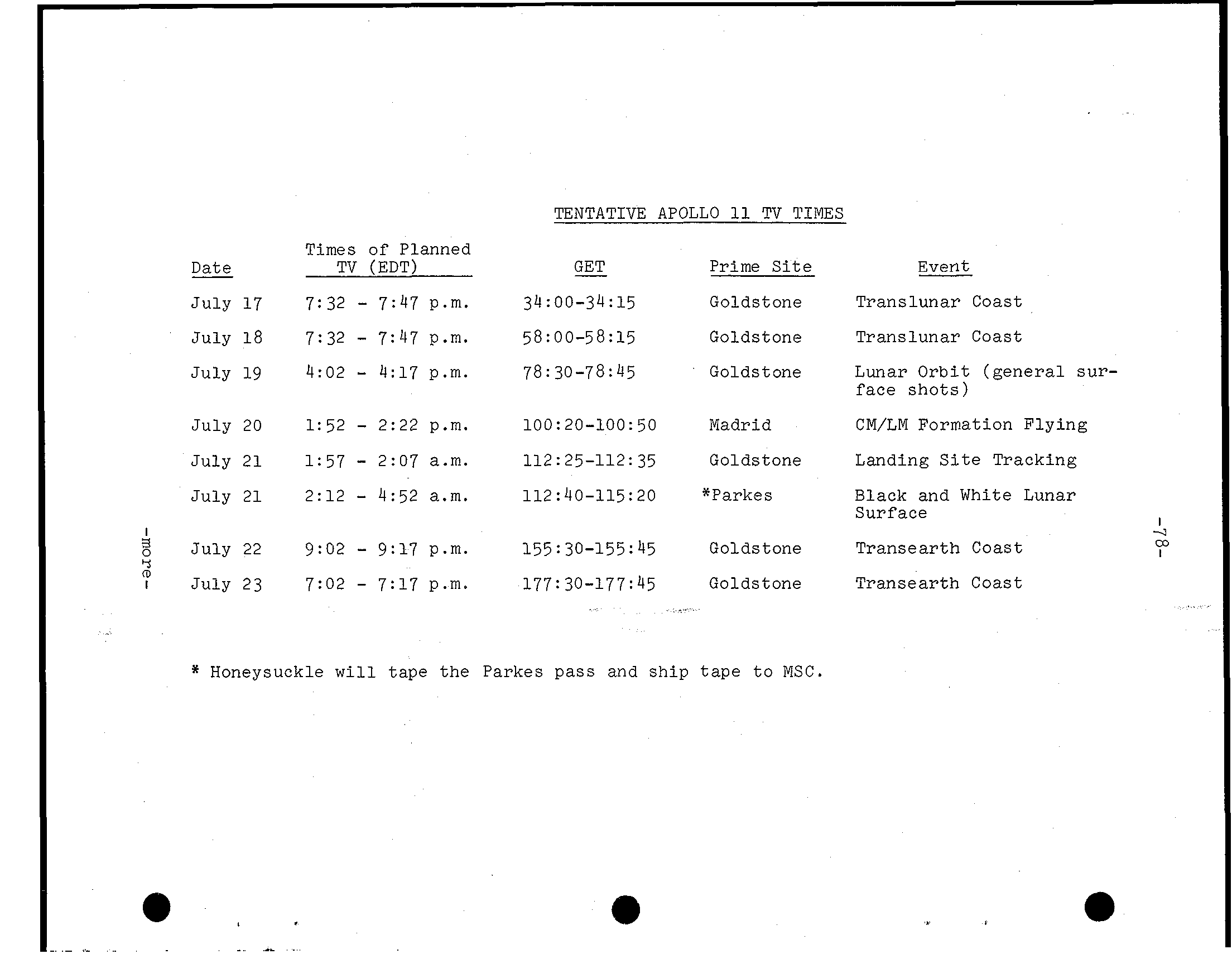
-77- APOLLO ONBOARD TELEVISION Two t e l e v i s i o n cameras w i l l c a r r i e d aboard Apollo A c o l o r camera of t h e type used on Apollo 1 0 w i l l b e stowed for use aboard t h e command module, and t h e black-and-white Apollo l u n a r t e l e v i s i o n camera w i l l be stowed i n t h e LM cent s t a g e for t e l e v i s i n g back to Earth a real-time r e c o r d of man's s t e p onto t h e Moon. The l u n a r t e l e v i s i o n camera weighs 7.25 pounds and draws 6.5 watts of 24-32 v o l t s D C power. Scan rate 1 0 frames-per- second 320 lines-per-frame. The camera body 10.6 inches long, 6.5 inches wide and 3.4 inches deep. The bayonet l e n s mount permits l e n s changes by a crewman i n p r e s s u r i z e d s u i t. Two l e n s e s, a wideangle l e n s for close-ups and l a r g e areas, and l u n a r day l e n s for viewing l u n a r s u r f a c e f e a t u r e s and a c t i v i t i e s i n n e a r f i e l d of view with s u n l i g h t i l l u m i n a t i o n, w i l l provided for l u n a r TV camera. The black-and-white l u n a r t e l e v i s i o n camera stowed i n MESA (Modular Equipment Stowage Assembly) i n t h e LM descent s t a g e and w i l l powered up b e f o r e Armstrong down t h e LM l a d d e r. When he p u l l s t h e lanyard to deploy t h e MESA, t h e TV camera w i l l a l s o swing down on t h e MESA to t h e left of t h e l a d d e r viewed from LM f r o n t) and r e l a y TV p i c t u r e of h i s i n i t i a l s t e p s on t h e Moon. Armstrong w i l l mount t h e TV camera on t r i p o d some d i s t a n c e away from t h e LM a f t e r Aldrin has descended to t h e s u r f a c e. The camera w i l l be untended to cover t h e crew's a c t i v i t i e s during t h e remainder of t h e EVA. The Apollo l u n a r t e l e v i s i o n camera b u i l t by Westinghouse E l e c t r i c Corp., Aerospace Division, Baltimore, Md. The c o l o r TV camera 12-pound Westinghouse camera with zoom l e n s for wideangle or close-up use, and has three- inch monitor which can be mounted on t h e camera or i n the command module. The c o l o r camera o u t p u t s standard 525-line, 30 frame-per-second s i g n a l i n c o l o r by use of r o t a t i n g c o l o r wheel. The black-and-white s i g n a l from t h e s p a c e c r a f t w i l l converted to c o l o r a t t h e Mission Control Center. The following a preliminary plan for TV passes upon a 9:32 a. m. EDT, J u l y 16 launch. -more-
TENTATIVE APOLLO TV TIMES Times of Planned Date TV (EDT) GET P r i m e S i t e Event - J u l y 17 7:32 7:47 p.m. 34:00-34:15 Goldstone T r a n s l u n a r Coast - J u l y 18 7:32 7:47 p.m. 58: 00-58: 15 Goldstone T r a n s l u n a r Coast - J u l y 19 4:02 4:17 p.m. 78:30-78:45 Goldstone Lunar O r b i t (g e n e r a l sur- face s h o t s) - J u l y 20 l: 5 2 2:22 p.m. 100: 20-100: 50 Madrid CM/LM Formation F l y i n g - J u l y 21 1:57 2:07 a.m. 112: 25-112: 35 Goldstone Landing S i t e Tracking - J u l y 21 2:12 4:52 a. m. 112:40-115:20 *Parkes Black and White Lunar Surface # - J u l y 22 9: 0 2 9:17 p.m. 155 30-155: 45 Golds tone T r a n s e a r t h Coast (D J u l y 23 7:02 7:17 p.m. 177: 30-177:45 Goldstone T r a n s e a r t h Coast * Honeysuckle w i l l t a p e t h e Parkes p a s s and s h i p t a p e t o MSC. m .. ..
-79- APOLLO 11 PHOTOGRAPHIC TASKS Still and motion pictures will be made of most spacecraft maneuvers as well as of the lunar surface and of crew activities in the Apollo 11 cabin. During lunar surface activities after lunar module touchdown and the two hour minute EVA, emphasis will be on photographic documentation of crew mobility, lunar surface features and lunar material sample collection. Camera equipment carried on Apollo 11 consists of one 70mm Hasselblad electric camera stowed aboard the command module, two Hasselblad 7Omm lunar surface superwide angle cameras stowed aboard the LM and a 35mm stereo close-up camera in the LM MESA. The 2.3 pound Hasselblad superwide angle camera in the LM is fitted with a 38mm f/4.5 Zeiss Biogon lens with a focusing range from 12 inches to infinity. Shutter speeds range from time exposure and one second to l/jOO second. The angular field of view with the 38mm lens is 71 degrees vertical and horizontal on the square-format film frame. The command module Hasselblad electric camera is normally fitted with an 80mm f/2.8 Zeiss Planar lens, but bayonet-mount 60mm and 25@mm lens may be substituted for special tasks. The 80mm lens has a focusing range from three feet to infinity and has a field of view of 38 degrees vertical and horizontal. Stowed with the Hasselblads are such associated items as a spotmeter, ringsight, polarizing filter, and film magazines. Both versions of the Hasselblad accept the same type film . magazine For motion pictures, two Maurer 1 6 m m data acquisition cameras (one in the CSM, one in the LM) with variable frame speed (1, 6, 12 and 24 frames per second) will be used. The cameras each weigh 2.8 pounds with a l3O-foot film magazine attached. The command module 1 6 m m camera will have lenses of 5, 18 and 75mm focal length available, while the LM camera will be fitted with the 18mn wideangle lens. Motion picture camera accessories include a right-angle mirror, a power cable and a command module boresight window bracket. -more-
-80- During the lunar surface extravehicular a c t i v i t y, the commander w i l l be filmed by the LM p i l o t with the LM 1 6 m m camera normal o r near-normal frame rates (2 4 and 1 2 f p s), but when he leaves the LM to j o i n the commander, he w i l l switch to one frame-per-second r a t e. The camera w i l l be mounted inside the LM looking through the right-hand window. The 18mm lens has horizontal f i e l d of view of 32 degrees and v e r t i c a l f i e l d of view of 23 degrees. A t one f p s, 130-fOot 16m maga- zine w i l l run out i n 87 minutes i n r e a l time; projected the standard 2 4 f p s, the film would compress the 87 minutes to 3.6 minutes. Armstrong and Aldrin w i l l use the Hasselblad lunar surface camera extensively during t h e i r surface EVA t o document each of t h e i r major tasks. Additionally, they w i l l make 360-degree overlapping panorama sequence of photos of the lunar hori- zon, photograph surface features i n the immediate area, make close-ups of geological samples and the area from which they were collected and record on film the appearance and condition of the lunar module a f t e r landing. Stowed i n the MESA 35mm s t e r e o close-up camera which shoots 2 4 m square color s t e r e o p a i r s with an image scale of one- half a c t u a l s i z e. The camera fixed focus and equipped with stand-off hood to position the camera t h e proper focus distance. A long handle permits an EVA crewman to position the camera without stooping f o r surface object photography. Detail small 40 microns can be recorded. A battery-powered e l e c t r o n i c f l a s h provides illumination. Film capacity minimum of 100 s t e r e o p a i r s. The s t e r e o close-up camera w i l l permit the Apollo landing crew t o photograph significant surface s t r u c t u r e phenomena which would remain i n t a c t only i n the lunar environment, such fine powdery deposits, cracks o r holes and adhesion of p a r t i c l e s. Near the end of EVA, the f i l m c a s e t t e w i l l be removed and stowed i n the commander's contingency sample container pocket and the camera body w i l l be l e f t on the lunar surface. -more-
-81- LUNAR DESCRIPTION - Terrain Mountainous and crater-pitted, fonner rising thousands of and the ranging f r o m few inches t o 180 miles i n diameter. The craters thought t o be formed by impact of meteorites. The surface covered wlth layer of fine-grained resembling o r sand, as well rocks and boulders. - Environment No no wlnd, and no moisture. The temperature ranges from 243 i n two-week lunar day t o 279 degrees below zero i n two-week lunar night. Gravity one-sixth of Earth. Micrometeoroids Moon (there is no atmosphere t o burn them up). Radiation might present problem during periods of unusual solar activity. - Dark Side The dark or hidden of Moon no longer is complete mystery. was photographed by a Russian craft and since then been photographed many times, particu- l a r l y by NASA's Lunar Orbiter spacecraft and Apollo - O r 1 i n There no agreement among scientists on or gin of the Moon. The theories: Moon once of Earth and off i n t o own orbit, evolved body Earth, and (3) formed elsewhere i n spaceand wandered u n t i l w a s captured by gravitational field. Physical Pacts t Mameter (about that of Earth) & Circumf erence 6,790 miles (about of Earth) Mstance from Earth 238,857 miles (mean; 221,463 minimum t o 252,710 maximum) Surf ace temperature +243OP (Sun zenith) -279OP (night) Surface 1/6 of of Earth 8 Volume 1/50th of Earth Lunar day and night 14 days Mean velocity i n orbit 2,287 miles hour Escape velocity miles per second Month (period of rotation around Earth) 27 days, 7 hours, 43 minutes -more-
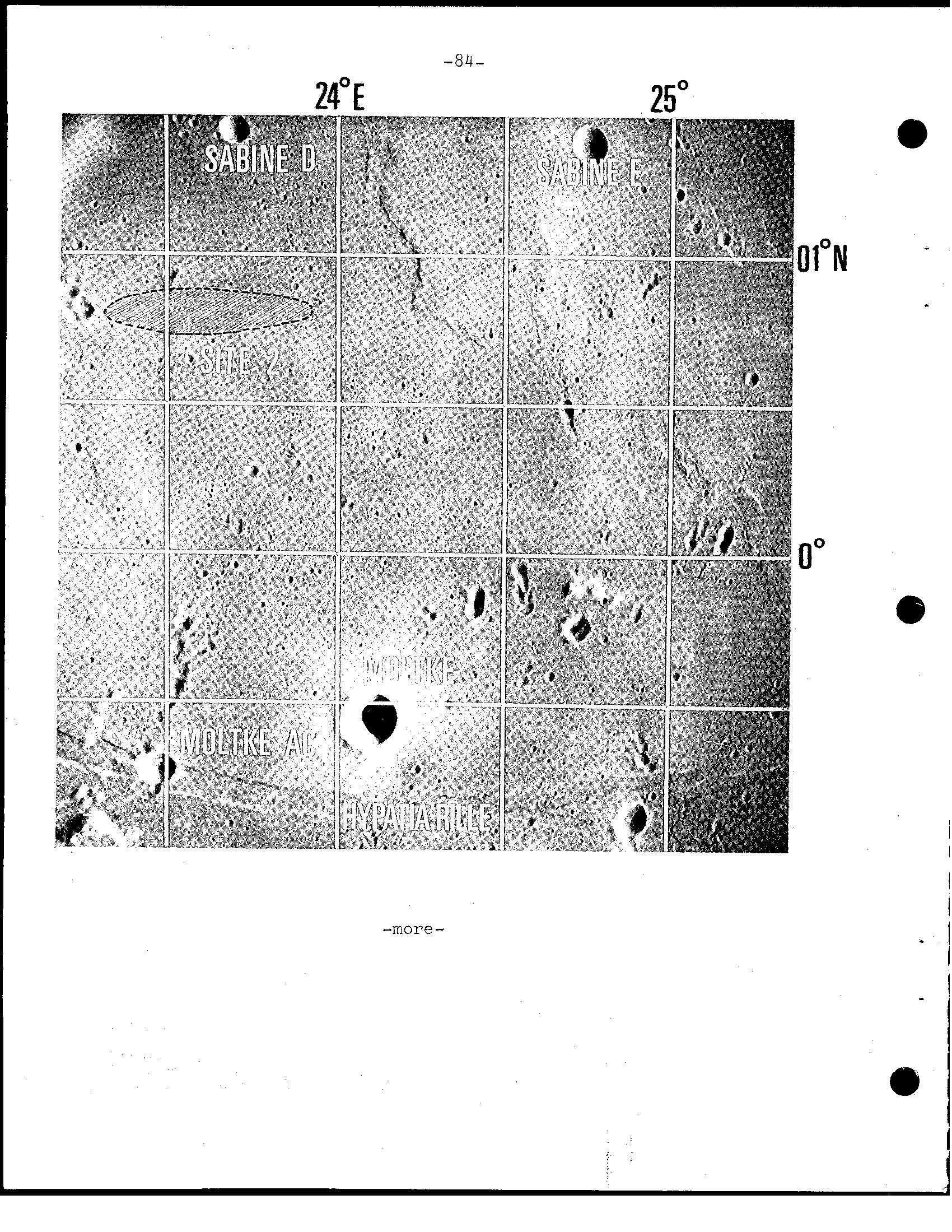
-82- Apollo Lunar Landing Sites Possible landing f o r the Apollo lunar module have been under study by NASA's Apollo Selection Board f o r more than two T h i r t y originally were considered. have been narrowed down t o three f o r lunar landing. (Site currently not considered f o r landing.) Selection of f i n a l was on resolution photographs by Lunar Orbiter spacecraft, plus close-up photos and surface provided by the Surveyor spacecraft which s o f t - landed on Moon. or1 i n a l are located on visible of the f Moon within 5 degrees and west of Moon's center and 5 degrees north and south of equator. The f i n a l site choices were based on factors: *Smoothness (relatively f e w and boulders) (no o r could cause incorrect altitude t o the lunar module landing radar) *Propellant requirements (selected require expenditure of spacecraft propellants) *Recycle (selected allow effective launch preparation recycling Apollo Saturn V countdown delayed) return (s i t e s w i t h i n of launched on return translunar trajectory) -- *Slope (there is slope than 2 In and landing area)
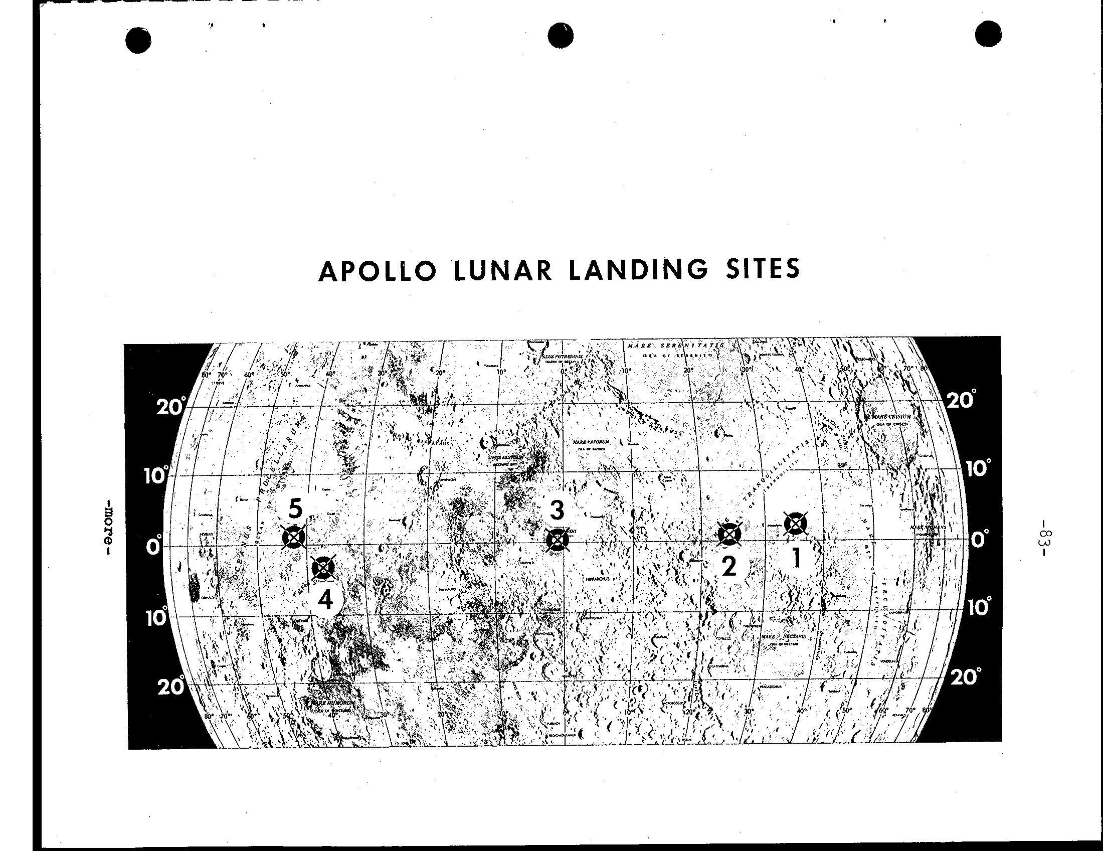
APOLLO LUNAR LANDING SITES
-84- -more-
-95- The Apollo 11 Landing Sites Are: Site 2 latitude o0 421 50" North longitude 23' 4 2 l 28"East Site 2 is located on the east central part of the Moon in south- western Mar Tranquillitatis. The site is approximately 62 miles (100 kilometers) east of the rim of Crater Sabine and approximately 118 miles (190 kilometers) south- west of the Crater Maskelyne. Site 3 latitude O o 2l.I 10" North longitude 1' 17' 57" West Site 3 is located near the center of the visible face of the Moon in the southwestern part of Sinus Medii. The site is approximately 2 5 miles (40 kilometers) west of the center of the face'and 2 1 miles (50 kilometers) southwest o f the Crater Bruce. Site 5 latitude 40' 4 1" North longitude 53' 57" West 4 1 O Site 5 is located on the west central part of the visible face in southeastern Oceanus Procel- larum. The site is approximately 130 miles (210 kilometers) south- west of the rim of Crater Kepler and 118 miles (190 kilometers) north northeast of the rim of Crater Flamsteed. -more-
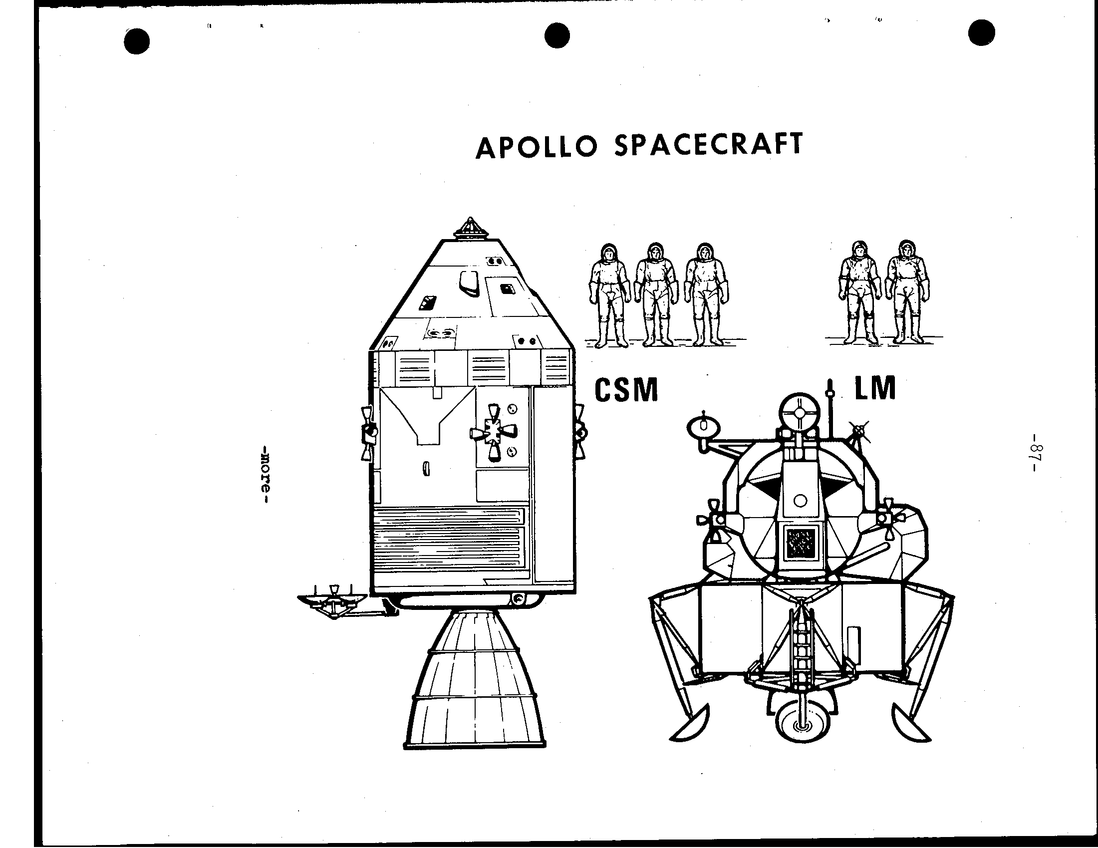
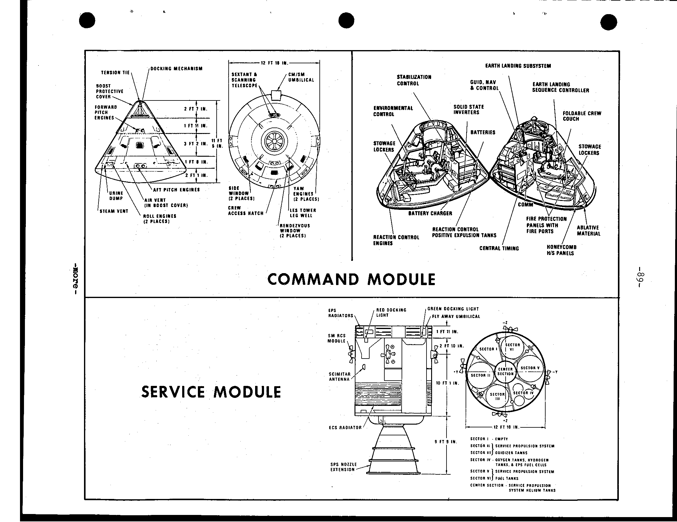
-86- COMMAND AND SERVICE MODULE STRUCTURE, SYSTEMS The Apollo spacecraft f o r t h e Apollo mission comprised of Command Module 107, Service Module 1 0 7, Lunar Module 5, spacecraft-lunar module adapter (SLA) and launch escape system. The SLA serves as a mating s t r u c t u r e between instrument u n i t atop t h e S-IVB stage of t h e Saturn V launch vehicle and housing f o r the module. Launch Escape System (LES) Propels command module t o s a f e t y i n an aborted launch. made up of an open-frame tower s t r u c t u r e, mounted t o the command module by four frangible b o l t s, and three solid-propellant rocket motors: a 147,000 pound-thrust launch excape s y s t e m motor, 2,400-pound-thrust p i t c h control motor, and a 31,500-pound-thrust tower j e t t i s o n motor. Two canard vanes n e a r the top deploy t o turn the command module aerodynamically t o an a t t i t u d e with t h e forward. Attached t o t h e of launch escape tower boost p r o t e c t i v e cover composed of r e s i n impregnated f i b e r g l a s s covered with cork, that p r o t e c t s command module from aerodynamic neating during boost and rocket exhaust from t h e main and j e t t i s o n motors. The system 33 four i n diameter t h e and weighs 8,910 pounds. -- Module (CM) S t r u c t u r e The b a s i c s t r u c t u r e of t h e command module pressure v e s s e l encased i n s h i e l d s, cone- shaped feet 5 inches high, diameter of 12 1 0 inches, and launch weight 12,250 pounds. The command module c o n s i s t s of t h e forward compartment which contains two r e a c t i o n c o n t r o l engines and components of Earth landing system; the crew compartment o r i n n e r pressure v e s s e l containing crew accomodations, controls and displays, and many of spacecraft systems; and compartment housing t e n reaction c o n t r o l engines, propellant tankage, helium tanks, water tanks, and the CSM umbilical The crew compartment contains 210 cubic of habitable volume. around t h e compartments of brazed s t a i n l e s s honeycomb w i t h an o u t e r layer of phenolic epoxy r e s i n an a b l a t i v e Shield thickness, varying according t o loads, ranges from 0. 7 inch the apex t o 2.7 inches t h e end. spacecraft i n n e r s t r u c t u r e of sheet-aluminum honey- comb bonded sandwhich ranging i n from 0.25 inch t h i c k forward access tunnel t o 1.5 inches t h i c k a t -more-
e a APOLLO SPACECRAFT
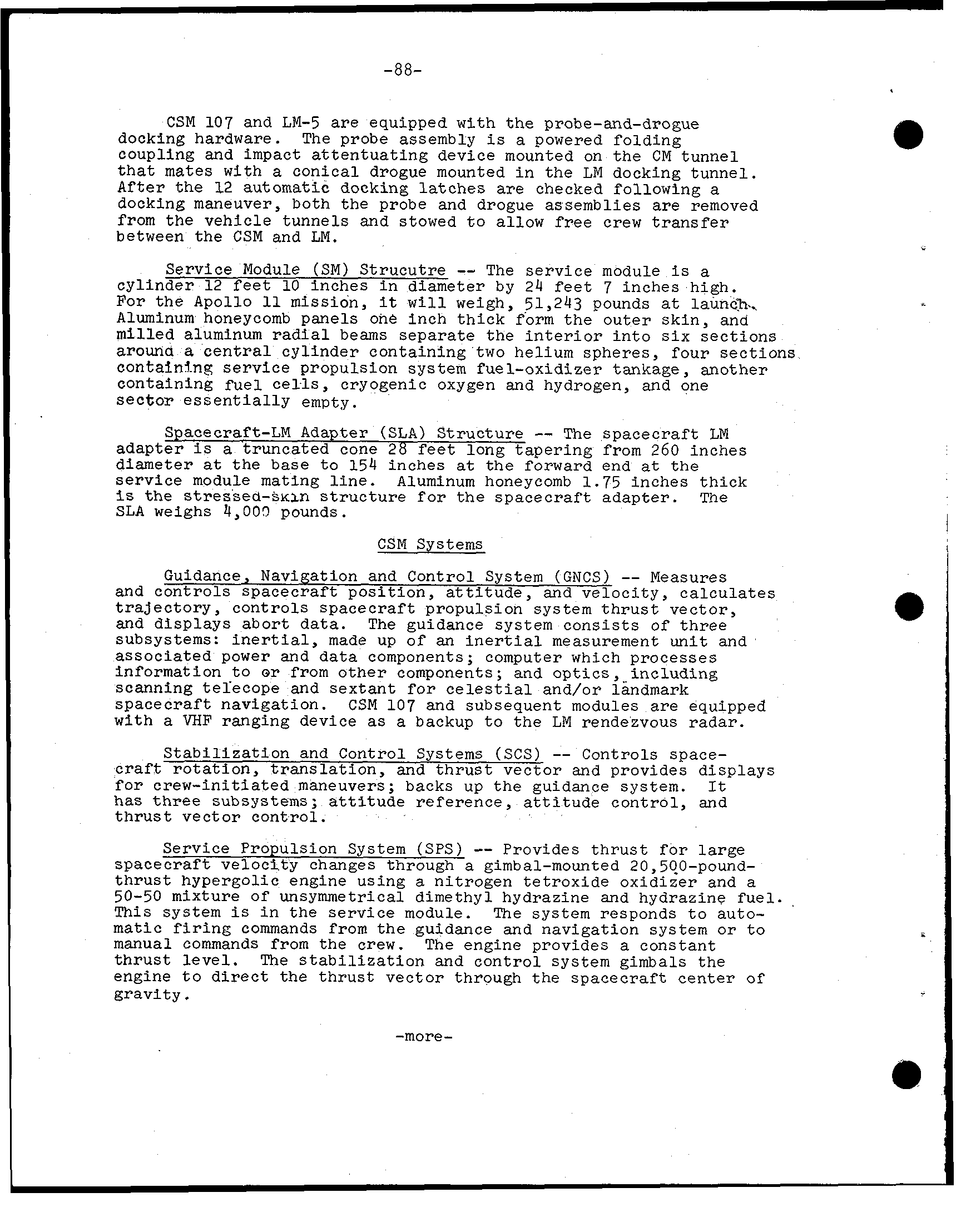
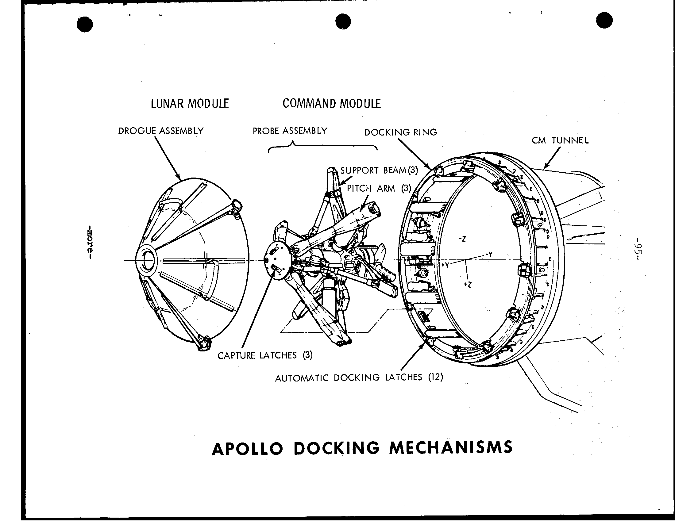
-88- CSM 107 and LM-5 a r e equipped w i t h the probe-and-drogue docking hardware. The probe assembly powered folding coupling and impact a t t e n t u a t i n g device mounted on CM tunnel t h a t mates with a conical drogue mounted i n t h e LM docking tunnel. 12 automatic docking l a t c h e s are checked following docking maneuver, both the probe and drogue assemblies are removed from t h e vehicle tunnels and stowed t o allow free crew t r a n s f e r between the CSM and LM. -- Service Module (SM) Strucutre The service module cylinder 12 f e e t 10 inches i n diameter by 24 f e e t 7 inches high. For t h e Apollo mission, it w i l l weigh, 51,243 pounds launch. Aluminum honeycomb Panels one inch thick form outer skin. and milled aluminum r a d i a l beams separate t h e i n t e r i o r i n t o s i x sections arouna c e n t r a l cylinder containing two helium spheres, four sections containjng Service propulsion system fuel-oxidizer tankage, another containing f u e l c e l l s, cryogenic oxygen and hydrogen, and one s e c t o r e s s e n t i a l l y empty. -- Spacecraft-LM Adapter (SLA) Structure The spacecraft LM adapter a truncated cone 28 feet long tapering from 260 inches diameter t h e t o 154 inches forward end service module mating l i n e. Aluminum honeycomb 1.75 inches thick s t r u c t u r e f o r the spacecraft The SLA 4,009 pounds. CSM Systems Guidance, Navigation and Control System (GNCS) Measures and controls spacecraft position, a t t i t u d e, and velocity, calculates t r a j e c t o r y, controls spacecraft D -~ roDulsion svstem t h r u s t vector. and-displays abort data. The guidance system consists of t h r e e > subsystems: i n e r t i a l, made up of an i n e r t i a l measurement u n i t and associated power and data components; computer which processes information t o o r from o t h e r components; and optics,,including scanning telecope and sextant f o r c e l e s t i a l and/or landmark spacecraft navigation. CSM 1 0 7 and subsequent modules a r e equipped w i t h VHF ranging device as a backup t o LM rendezvous radar. S t a b i l i z a t i o n and Control Systems (SCS) Controls space- c r a f t r o t a t i o n, t r a n s l a t i o n, and t h r u s t vector and provides displays f o r crew-initiated maneuvers: backs UD guidance s v s t e m. subsystems; a t t i t u d e reference, a t t i t u d e control, and t h r u s t vector control. -- Service Propulsion System (SPS) Provides t h r u s t f o r large spacecraft velocity changes through gimbal-mounted 20.50 0-uo und - t h r u s t hypergolic engine-using nitrogen tetroxide oxidizer and 50-50 mixture of unsymmetrical dimethyl hydrazine and hydrazine fuel. system i n t h e service module. system responds t o auto- matic f i r i n g commands from guidance and navigation system or t o manual commands from the crew. The engine provides constant t h r u s t l e v e l. The s t a b i l i z a t i o n and control system the engine t o d i r e c t the t h r u s t vector through t h e spacecraft center of gravity. -more-
a EARTH SUBSYSTEM STABILUATION \ CONTROL GUID. NAY ElRlH LUOING 6 CONTROL\ SEOUENCE COMlROLUR COMMAND MODULE SERVICE MODULE
-90- Telecommunications System Provides voice, television, t e l e - metry, and command data and tracking and ranging between the space- c r a f t - a n d Earth, between the command module and-the lunar moduie and between the spacecraft and the extravehicular astronaut. It a l s o provides intercommunications between astronauts. The t e l e - communications system consists of pulse code modulated telemetry f o r relaying t o Manned Space Flight Network s t a t i o n s on space- c r a f t systems and crew condition, VHF/AM voice, and unified S-Band tracking transponder, air-to-ground voice communications, onboard television, and VHF recovery beacon. Network s t a t i o n s can transmit to the spacecraft such items updates t o t h e Apollo guidance computer and c e n t r a l timing equipment, and real-time commands for c e r t a i n onboard functions. The high-gain steerable S-Band antenna consists of four, 31-inch-diameter parabolic dishes mounted on folding boom the aft end of the service module. Nested alongside the service propulsion system engine nozzle u n t i l deployment, the antenna swings out angles t o t h e spacecraft longitudinal axis, w i t h the boom pointing 52 degrees below the heads-up horizontal. Signals from t h e ground s t a t i o n s can be tracked e i t h e r automatically or manually with t h e antenna’s gimballing system. Normal S-Band voice and uplink/downlink communications w i l l by the omni and high-gain antennas. Sequential System Interfaces w i t h other spacecraft systems and subsystems t o i n i t i a t e time c r i t i c a l functions during launch, docking maneuvers, sub-orbital aborts, and entry portions of mission. The system a l s o controls routine spacecraft sequencing such service module separation and deployment of the E a r t h land- i n g system. Emergency Detection System (EDS) Detects and displays t o the crew launch vehicle emergency conditions. such excessive pitch or r o l l r a t e s or two enginks o u t, and automatically o r manually shuts down t h e booster and a c t i v a t e s the launch escape system; functions u n t i l t h e spacecraft i n o r b i t. E a r t h Landing System (ELS) Includes the drogue and main parachute system as well post-landing recovery In normal entry descent, the command module forward heat s h i e l d j e t t i s o n e d 24,000 f e e t, permitting mortar deployment of two reefed 16.5-foot diameter drogue parachutes for orienting and decelerating t h e spacecraft. After disreef and drogue release, three mortar deployed p i l o t chutes p u l l out the three main 83.3- foot diameter parachutes w i t h two-stage reefing to provide gradual i n f l a t i o n i n three steps. Two main parachutes out of three can provide safe landing. -more-
a Crewmen optical alignment sight LM mounted CSM-active docking alignment targe VHF EVA antenna steerable antenna CSM mounted LM-active docking alignment target Two scimitar VHF omni antennas on SM (180 deg. apart) SPACECRAFT AXIS AND ANTENNA LOCATIONS
VHF inflight antenna (2) Steerable S-band 2-GHz high gain antenna S-band steerable antenna 7 S-band Four S-band omni 4 I Two scimitar VHF omni antennas on SM (180 deg. apart) Rendezvous radar forward heat shield (Not Shown) SPACECRAFT AXIS AND ANTENNA LOCATIONS a
-93- Reaction Control System (RCS) The command module and the service module each has own independent system. The SM RCS f o u r i d e n t i c a l RCS "quads" mountea &round the SM 90 degrees a p a r t. Each quad has f o u r 100 pound-t3rust engines, tdo f u e l and two o x i d i z e r tanks and helium pressurization sphere. SM RCS provides redundant spacecraft a t t i t u d e control through cross- coupling l o g i c inputs from the s t a b i l i z a t i o n and guidance systems. Small velocity change maneuvers can a l s o be made w i t h the SM RCS. The CM RCS c o n s i s t s of two independent six-engine subsystems of s i x 93 pound-thrust engines each. Both subsystems are a c t i v a t e d j u s t p r i o r to CM separation from the SM: one used f o r spacecraft a t t i t u d e control during e n t r y. The o t h e r serves i n standby as a backup. Propellants for both CM and SM RCS are monomethyl hydrazine f u e l and nitrogen t e t r o x i d e oxidizer with helium pressurization. These propellants a r e hypergolic, they burn spontaneously when combined without an i g n i t e r. -- E l e c t r i c a l Power System (EPS) Provides e l e c t r i c a l energy sources, power generation and c o n t r o l, power conversion and condition- ing, and power d i s t r i b u t i o n t o t h e spacecraft throughout the mission. The EPS a l s o furnishes drinking t o astronauts as by- product of f u e l c e l l s. The primary source of e l e c t r i c a l power t h e f u e l mounted i n t h e SM. Each c e l l c o n s i s t s of hydrogen compartment, an oxygen compartment, and two electrodes. The cryogenic gas storage system, a l s o located i n the SM, supplies t h e hydrogen and oxygen used i n f u e l c e l l power plants, w e l l oxygen used i n the ECS. Three silver-zinc oxide storage supply power to t h e CM during entry and landing, provide power for sequence con- t r o l l e r s, and supplement t h e f u e l c e l l s during periods of peak power demand. These batteries located i n the CM lower equip- ment bay. A b a t t e r y charger located i n the same bay t o assure f u l l charge p r i o r to e n t r y. Two other silver-zinc oxide independent of and completely i s o l a t e d from the rest of t h e dc power system, used to supply power for explosive devices for CM/SM separation, parachute deployment separation, third-stage separation, launch excape system tower separation, and o t h e r pyrotechnic uses. Environmental Control System (ECS) Controls spacecraft atmosohere. oressure. and temverature and manaEes water. I n ~ ~ ~~~ ~~ addition t o regulatiAg cabin and s u i t pressure, temperature and humioity, the system removes carbon dioxide, odors and p a r t i c l e s, and v e n t i l a t e s the cabin landing. c o l l e c t s and s t o r e s f u e l potable water f o r crew use, supplies water to the glycol evaporators for cooling, and dumps surplus overboard through the urine dump valve. Proper operating temDerature of e l e c t r o n i c s and e l e c t r i c a l equipment maintained by t h l s System through t h e use of cabin heat exchangers, the space r a d i a t o r s, and the glycol evaporators. -more-
-94- Recovery aids include t h e uprighting system, swimmer i n t e r - e phone connections, sea dye marker, flashing beacon, VHF recovery beacon, and VHF transceiver. The uprighting system consists of three compressor-inflated bags t o upright the spacecraft should land i n the water apex down (s t a b l e I1 position). Caution and Warning System Monitors spacecraft systems for out-of-tolerance conditions and a l e r t s crew by v i s u a l and audible so t h a t crewmen may trouble-shoot the problem. - Controls and Displays Provide readouts and control functions of a l l other spacecraft systems i n the command and service modules. A l l controls are designed t o be operated by crewmen i n pressurized s u i t s. Displays are grouped by system and located according t o the frequency the crew r e f e r s t o them.
a LUNAR MODULE COMMAND MODULE > DROGUE ASSEMBLY PROBE ASSEMBLY DOC RING CM TUNNEL APOLLO DOCKING MECHANISMS
-96- LUNAR MODULE STRUCTURES, WEIGHT The lunar module a two-stage vehicle designed for space operations near and on the Moon. The LM incapable of reentering the atmosphere. lunar module stands 22 feet inches high and 31 feet wide (diagonally across landing gear). Joined by four explosive bolts and umbilicals, the cent and descent stages of LM operate unit until staging, when ascent stage functions single space- craft for rendezvous and docking with the CSM. Ascent main sections make up the ascent stage: the crew compartment, midsection, and equipment bay. Only the crew compartment and midsection are Pressurized (4.8 psig; 337.4 cm) of LM cabin; other sections of LH unpressurized. cabin volume 235 cubic (6.7 cubic ascent stage measures 12 feet 4 inches high by 14 inch i n Structurally, the ascent stage six substructural crew compartment, midsection, equipment bay, thrust chamber cluster supports, antenna supports and thermal and micrometeorold cylindrical crew compartment I s semimonocoque structure of machined longerons and fusion-welded aluminurn and 92 inches (2.35 m) i n diameter and 42 inches (1.07 m) Two flight stations are equipped w i t h control and dis- play panels, body restraints, landing two front an ov e rhead docking nindow, an alignment optical telescope the center between two flight stations. volume 160 aubic Two triangular front windows and 32-inch m) square inward-opening forward hatch are i n the crew compartment front External structural beams support crew compartment and serve to support lower interstage mounts lower ends. Ring-stiffened semhonocoque construction is em- ployed In the midsection, with chem-milled aluminum skin over fusion-welded longerone and stiffeners. Fore-and-aft beams across top of the midsection join with those running across the top of the cabin to take ascent stage loads i n isolate the cabin from - -more
-97- DOCKING 2 1 LUNAR SURFACE SENSING PROBE (3) APOLLO LUNAR MODULE -more-
VHF ANTENNA(2) ERHEAD HATCH VA ANTENNA ALIGNMENT OPTICAL TELESCOPE OCKING TARGET RECESS RENDEZVOUS GASEOUS OXYGEN TANK (2) RADAR ANTENNA AFT EQUIPMENT BAY REPLACEABLE ELECTRONIC ASSEMBLY FUEL TANK (REACTION CONTROI B ASCENT ENGINE COVER LIQUID OXYGEN TANK s. -BAND INFLIGHT ANTENNA @), TRACKING LIGHT (REACTION CONTROL) REACTION CONTROL ASSEMBLY(4 PLACES) OXIDIZER TANK (REACTION CONTROL) N GRESS/EGRESS HATCH CREW COMPARTMENT ,. - APOLLO LUNAR MODULE ASCENT STAGE a
LM C A B I N INTERIOR, LEFT H A L F
iOSE CABIN INTERIOR, RIGHT HALF
-101- The ascent stage engine compartment formed by two beams running across the lower midsection deck and mated t o the fore and bulkheads. Systems located i n the midsection include the LM guidance computer, the power and servo assembly, ascent engine propellant tanks, RCS pro- pellant tanks, the environmental control system, and the waste management section. A tunnel atop the ascent stage meshes with command module docking latch During docking, the CM docking and latches aligned by the LM drogue and the CSM probe. The docking tunnel extends downward into the midsection 16 inches (40 cm). The tunnel 32 inches cm) i n dia- meter and used for crew transfer between CSM and LM. The upper hatch on the inboard end of docking tunnel downward and cannot be opened with the LM pressurized and undocked. A thermal and micrometeoroid of multiple of mylar and single thickness of thin aluminum skin encases the entire ascent structure. Descent The descent stage consists of cruciform load-carrying structure of two of upper and lower decks, -- and enclosure bulkheads of conventional skin-and-stringer aluminum alloy construction. center compartment houses the descent engine, and descent propellant tanks are housed i n four square around the engine. The descent measures feet 7 inches high 14 feet inch In Four-legged outriggers mounted on the ends of each pair of beams serve SLA attach points and "knees" for the landing gear main Triangular bays between the main beams enclosed into quadrants housing such components the ECS water tank, helium tanks, descent engine control assembly of the guidance, navi- gation and control subsystem, ECS gaseous oxygen tank, and batteries for the electrical power system. Like the ascent stage, the descent stage i s encased i n the mylar and aluminum alloy thermal and micrometeoroid LM external platform, or "porch", mounted on the forward outrigger j u s t below forward hatch. A ladder ex- tends down the forward landing gear from the porch for crew lunar surface operations. - -more
Y I PAD (4) LUNAR SURFACE SENSING PROBE (3) Bb
-103- I n retracted position until a f t e r crew m a n s LM, the landing s t r u t s are explosively extended and provide surface landing Impact attenuation. main are with crushable aluminum honeycomb f o r absorbing compression loads. Footpads 37 inches (0.95 m) i n diameter a t end of each landing provide vehicle "floatation"on the lunar surface. Each pad (except forward with lunar- surface sensing probe which signals crew t o shut down the descent engine upon contact with the lunar surface. LM-5 flown on Apollo mission w i l l have a weight of 33,205 pounds. The weight breakdown is as follows: Ascent 4,804 Includes water and oxygen; no Descent 4,483 C*W RCS propellants (loaded) 604 lbs. DPS propellants (loaded) APS propellants (loaded) 5,214 33,205 lbs. Lunar Module Systems -- Electrical Power System LFI DC e l e c t r i c a l system -- of six s i l v e r zinc primary four i n descent two in the ascent with own e l e c t r i c a l control (ECA). Power from primary pass through c i r c u i t to energize the IM DC buses, f r o m which 28-volt Dc power distributed through c i r c u i t t o IM systems. AC power (117~ 40 0Hz) is supplied by two inverters, of which can supply spacecraft AC to AC -- Environmental Control System Consists of the atmosphere revitalization section. oxvgen su - p - v l - u and cabin pressure Control section, water management, transport section, and o u t l e t s for oxy en and servicing of Portable L i f e Support System $PLss). - -more
-104- Components of the atmosphere revitalization section are the suit circuit assembly which cools and ventilates the pressure garments, reduces carbon dioxide levels, removes odors, noxious gases and excessive moisture; the cabin re- circulation assembly which ventilates and controls cabin atmosphere temperatures; and the steam flex duct which vents to space steam from the suit circuit water evaporator. The oxygen supply and cabin pressure section supplies gaseous oxygen to the atmosphere revitalization section for maintaining suit and cabin pressure. The descent stage oxygen supply provides descent flight phase and lunar stay oxygen needs, and the ascent stage oxygen supply provides oxygen needs for the ascent and rendezvous flight phase. Water for drinking, cooling, fire fighting, food pre- paration, and refilling the PLSS cooling water servicing tank is supplied by the water management section. The water is contained in three nitrogen-pressurized bladder-type tanks, one of 367-pound capacity in the descent stage and two of 47.5-pound capacity in the ascent stage. The heat transport section has primary and secondary water-glycol solution coolant loops. The primary coolant loop circulates water-glycol for temperature control of cabin and suit circuit oxygen and for thermal control of batteries and electronic components mounted on cold plates and rails. If the primary loop becomes inoperative, the secondary loop circulates coolant through the rails and cold plates only. Suit circuit cooling during secondary coolant loop operation is provided by the suit loop water boiler. Waste heat from both loops is vented overboard by water evaporation or sub- limators. -- Communication System Two S-band transmitter-receivers, two VHF transmitter-receivers, a signal processing assembly, and associated spacecraft antenna make up the ILM communications system. The system transmits and receives voice, tracking and ranging data, and transmits telemetry data on about 270 measurements and TV signals to the ground. Voice communica- tions between the LM and ground stations is by S-band, and between the LM and CSM voice is on VRF. - I -more
-105- Although no real-time commands can be sent t o LM-5 and a subsequent spacecraft, the uplink is retained t o pro- cess guidance officer commands transmitted from Mission Control Center t o the LM guidance computer, such as state vector updates. The storage electronics assembly (DSEA) is a four- channel voice recorder with timing signals with 10-hour recording capacity which will brough back into the CSM II f o r return t o Earth. DSEA recordings cannot be dumped"t o ground stations. LM antennas one 26-inch diameter parabolic S-band steerable antenna, two S-band inflight antennas, two VHF inflight antennas, and an erectable S-band antenna (optional) for lunar surface. -- Guidance, Navigation and Control System Comprised of sections: primary guidance and navigation section (PONS), abort guidance-section (AGS), section, control electronics section (CES), and orbital rate drive electronics for Apollo and LM (ORDEAL). * The ENS an inertial guidance system updated alignment optical telescope, an inertial measurement unit, and rendezvous and landing The pro- vides inertial reference for computations, produces inertial alignment reference by feeding optical sighting data into LM guidance computer, position and velocity data, computes LM-CSM rendezvous from radar inputs, con- trols attitude and thrust t o maintain LM trajectory, and controls descent engine throttling and The LM-5 guidance computer has the Luminary I A software program for processing landing radar altitude and velocity information for lunar landing. LM-4, flown on Apollo not have the landing i n guidance computer Luminary program. * AGS an independent backup for PONS, having own inertial sensors and computer. * The section made up of rendezvous which provides CSM range and range and line-of-sight angles for maneuver computation to the LM guidance computer; the landing which provide altitude and velocity data t o the v guidance computer during lunar landi rendezvous 6 an operating range from 80 feet t o 4 nautical miles. range transfer tone assembly, utilizing VHF electronics, passive responder to the CSM VHP ranging device and a backup to the rendezvous - -more
-136- CES controls LM attitude and translation about a l l axes. controls by PGNS command the automatic operation of the ascent and descent engines, and the reaction control thrusters. Manual attitude controller and thrust-translation controller commands are also handled by CES. * ORDEAL, displays on f l i g h t director attitude in- dicator, the computed local vertical in the pitch during circular or lunar orbits. -- Reaction Control System The LPI four RCS engine clusters of four 100-pound (45.4 kR) enaines each which use helium-pressurized hypergolic propellants. oxidizer nitrogen tetroxide, fuel Aerozine 50 (50/50 blend of hydrazine and unsymmetrical dimethyl hydrazine). Propellant plumbing, valves and pressurizing components i n two parallel, independent systems, each feeding the engines i n each cluster. Either capable of maintaining attitude alone, but one supply system propellant allows system t o supply 16 engines. Additionally, interconnect valves permit RCS system t o draw from ascent engine propellant tanks. engine clusters mounted on outriggers 90 degrees on the ascent RCS provides stabilizing during ascent and descent burns, controls LM attitude during maneuvers, and produces thrust for separation, and ascent/descent engine tank ullage. operated i n pulse or modes. -- Descent Propulsion System Maximum thrust of descent engine 9,870 pounds (4,380.9 kg) and throttleable between 1,050 pounds (476.7 kg) and 6,300-pounds (2,860.2 kg). The engine can six i n any direction i n response t o attitude commands and f o r offset center of gravity Propellants are helium-pressurized Aerozine 50 and . nitrogen t roxide -- Ascent Propulsion System The 3,500-pound (1,589 kg) thrust ascent engine not gimbaled and perfoms f u l l thrust. The engine remains d o m n t u n t i l ascent from descent Propellants the as burned by the RCS engines and the descent engine. -- Caution and Controls and Displays These two have the same function aboard lunar module they do aboard the command module. (See CSM section.) -more-
-107- -- Tracking and Docking Lights A flashing tracking l i g h t (once second, milliseconds duration) on front face of the lunar module an a i d f o r contingency CSM-active rendezvous IM rescue. V i s i b i l i t y ranges from 400 nautical miles through the CSM sextant t o 130 miles with naked eye. Five docking l i g h t s analagous to a i r c r a f t running l i g h t s mounted on LM f o r CSM-active rendezvous: two forward yellow lights, a f t white light, port l i g h t and starboard green A l l docking l i g h t s have about a 1,000-foot . v i s t y - -more
-108- SATURN V LAUNCH VEHICLE DESCRIPTION AND OPERATION The Apollo spacecraft w i l l be boosted i n t o Earth orbit and then onto lunar trajectory by the sixth Saturn V launch vehicle. The 281-foot high Saturn V generates enough t h r u s t t o place a 125-ton payload i n t o 105 nm Earth orbit or boost about 50 tons t o lunar orbit. Saturn V, developed by the NASA-Marshall Space Flight Center, underwent research and development testing i n the"all-up" mode. From the launch stages have been live. T h i s resulted i n"man of the Saturn V i n two launches. The t h i r d Saturn V (AS-503) carried Apollo 8 and crew on a lunar orbit mission. Saturn V rockets were launched November 9, 1967, April 4, 1968, December 21, 1968, March 3, 1969, and May 18, 1969. The two space vehicle were unmanned; the three carried the Apollo 8, 9 and 30 crews, respectively. Launch Vehicle Range Safety Provisions In the event of an imminent emergency during the launch vehicle powered f l i g h t phase could become necessary t o abort the mission and remove the command module and crew from immediate danger. After providing f o r crew safety, the Range Safety Officer may take further action the remaining i n t a c t vehicle constitutes hazard t o overflown geographic areas. Each launch vehicle propulsive stage is equipped with propellant dispersion system t o terminate the vehicle f l i g h t i n safe location and disperse propellants with minimized ignition probability. A transmitted ground command shuts down engines and second command detonates explosives which open f u e l oxidizer tanks enabling the propellants t o disperse. On each stage the tank cuts are made i n non-adjacent areas t o minimize propellant mixing. The stage propellant dispersion systems are by ground command. -more-
-109- SATURN V LAUNCH VEHICLE FIRST STAGE (S-IC) DIAMETER-33 FEET HEIGHT 138 FEET WEIGHT 5,022,674 LBS. FUELED . 288,750 LBS DRY ENGINES FIVE F-l ., PROPELLANTS- LIQUID OXYGEN (3,307,855 LBS 346,372 GALS .) RP-I (KEROSENE) - (1,426,069 LBS., 212,846 GALS.) THRUST 7,653,854 LBS. AT LIFTOFF ZFCOND STAGE 6-11) DIAMETER-33 FEET 6 - I V B) HEIGHT 81.5 FEET WEIGHT 1,059,171 LBS. FUELED 79,918 LBS. DRY ENGINES FIVE J-2 PROPELLANTS-LIQUID OXYGEN (821,022 LBS., 85,973 GALS.) LIQUID HYDROGEN SECOND STAGE (158,221 LBS., 282,555 GALS.) THRUST 1,120,216 TO 1,157,707 LBS. (S-11) INTERSTAGE- 1,353 (SMALL) 8,750 (LARGE) THIRD STAGE (S-IVB) DIAMETER-21.7 FEET HEIGHT 58.3 FEET WEIGHT 260,523 LBS. FUELED 25,000 LBS. DRY ENGINES ONE J-2 PROPELLANTS-LIQUID OXYGEN (192,023 LBS., FIRST STAGE 20,107 GALS.) LIQUID HYDROGEb (43,500 LBS., 77,680 GALS.) (S-IC) THRUST 178,161 TO 203,779 LBS. INTERSTAGE-8,081 LBS. _ - ~ INSTRUMENT UNIT DIAMETER-21.7 FEET HEIGHT 3 FEET WEIGHT 4,306 LBS. NOTE: WEIGHTS AND MEASURES GIVEN ABOVE ARE FOR THE NOMINAL VEHICLE CONFIGURATION FOR APOLLO 11. THE FIGURES MAY VARY SLIGHTLY DUE TO CHANGES BEFORE LAUNCH TO MEET CHANGING CONDITIONS. WEIGHTS NOT INCLUDED ABOVE ARE FROST AND MISCELLANEOUS SMALLER ITEMS.
-110- SPACE VEHICLE WEIGHT SUMMARY (pounds) Event W t. Chg. Veh. W t. A t i g n i t i o n 6,484,280 Thrust buildup p r o p e l l a n t used 85,745 A t motion 6,398,535 S-IC f r o s t 650 S-IC n i t r o g e n purge 37 s-I1 f r o s t 450 S-I1 i n s u l a t i o n purge gas 1 2 0 S-IVB f r o s t 200 Center engine decay p r o p e l l a n t used 2,029 Center engine expended p r o p e l l a n t 406 S-IC mainstage p r o p e l l a n t used 4,567,690 Outboard engine decay p r o p e l l a n t used 8,084 S-IC s t a g e drop weight 363,425 S-IC/S-I1 small i n t e r s t a g e 1,353 S-I1 u l l a g e p r o p e l l a n t used 73 A t S-IC s e p a r a t i o n 1,454,014 S-I1 t h r u s t buildup p r o p e l l a n t used 1,303 S-I1 start t a n k 25 S-I1 u l l a g e p r o p e l l a n t used 1,288 S-I1 mainstage p r o p e l l a n t and venting 963,913 Launch escape tower 8,930 S-I1 aft i n t e r s t a g e 8,750 S-I1 t h r u s t decay p r o p e l l a n t used 4 80 S-I1 s t a g e drop weight 94,140 S-II/S-IVB i n t e r s t a g e 8,081 S-IVB a f t frame dropped lr8 S-IVE d e t o n a t o r package 3 A t S-II/S-IVB s e p a r a t i o n 367,053 S-IVB u l l a g e rocket p r o p e l l a n t 96 A t S-IVB i g n i t i o n 366,957 S-IVB u l l a g e p r o p e l l a n t 22 S-IVB hydrogen i n tank 4 T h r u s t buildup p r o p e l l a n t 436 S-IV3 mainstage p r o p e l l a n t used 66,796 S-IVS u l l a g e r o c k e t cases 135 S-IVB APS p r o p e l l a n t 2 A t f i r s t S-IVE c u t o f f s i g n a l 299,586 Thrust decay p r o p e l l a n t used 89 APS p r o p e l l a n t (u l l a g e) 5 Engine p r o p e l l a n t l o s t 30 A t parking o r b i t i n s e r t i o n 299,562 Fuel t a n k v e n t 2,879 APS p r o p e l l a n t 235 Hydrogen t a n k 2 O2/H2 burner 16 LOX tank vent 46 S-IVB f u e l l e a d l o s s 5 -more-
-111- - Event W t. Chg. Veh. W t. A t second S-IVB i g n i t i o n S-IVB hydrogen i n tank Thrust buildup p r o p e l l a n t 569 S-IVB mainstage p r o p e l l a n t used 164,431 8 APS p r o p e l l a n t used A t second S-IVB c u t o f f signal 139,533 Thrust decay p r o p e l l a n t used 124 Engine p r o p e l l a n t l o s t 40 A t t r a n sl u n a r i n j e c ti o n 139,369 a . -more- l -
-112- F i r s t The 7.6 million pound t h r u s t (S-IC) was developed j o i n t l y by the National Aeronautics and Space Administration's Space Flight Center and the Boeing Co. The Center assembled four S-IC stages: a s t r u c t u r a l t e s t model, s t a t i c t e s t version, and the two f l i g h t stages. Subsequent f l i g h t stages a r e assembled by Boeing at Michoud Assembly F a c i l i t y, New Orleans. The S-IC f o r t h e Apollo mission was t h e t h i r d f l i g h t booster t e s t e d the NASA-Mississippi Test F a c i l i t y. The S-IC t e s t MTF was on May 1967, second on August 9, 1967, and the third--the booster f o r Apollo 11--was on August 6, 1968. E a r l i e r f l i g h t stages were s t a t i c f i r e d the Marshall Center. The booster stage stands 138 f e e t high and 33 i n diameter. Major s t r u c t u r a l components include t h r u s t s t r u c t u r e, f u e l tank, intertank s t r u c t u r e, oxidizer tank, and forward s k i r t. f i v e engines burn kerosene (RP-1) f u e l and l i q u i d oxygen. The weighs 288,750 empty and 5,022,674 pounds fueled. Normal propellant flow r a t e t o f i v e F-1 engines 29,364.5 pounds (2,230 gallons) per second. Four of t h e engines are mounted on ring, 90 degree i n t e r v a l s. These four gimballed t o control the rocket's d i r e c t i o n of f l i g h t. The engine mounted r i g i d l y i n t h e center. Second Stage The Space Division of North American Rockwell Corp. builds the million pound t h r u s t S-I1 Beach, California. The 81 fo o t 7 inch long, 33 foot diameter stage made up of the forward s k i r t t o which the t h i r d attaches, t h e l i q u i d hydro- gen tank, l i q u i d oxygen tank (separated from t h e hydrogen tank by an insulted common bulkhead), the t h r u s t s t r u c t u r e on which the engines mounted, and an i n t e r s t a g e section t o which stage attaches. Five J-2 engines power the S-11. The outer four engines equally spaced on 17.5 foot diameter c i r c l e. These four engines may gimballed through plus o r minus seven-degree square p a t t e r n f o r t h r u s t vector control. A s on the center engine (number 5) mounted on t h e stage centerline fixed i n position. The second (S-111, l i k e uses high performance 5-2 engines l i q u i d oxygen and l i q u i d hydrogen. * The stage's purpose t o provide stage boost almost t o Earth o r b i t. -more-
-113- The f o r Apollo was s t a t i c t e s t e d by North American Rockwell at the NASA-Mississippi Test F a c i l i t y on September 3, 1968. This stage was shipped t o t e s t s i t e v i a the Panama Canal f o r the t e s t f i r i n g. Third Stage The t h i r d stage (S-IVa) was developed by t h e McDonnell Douglas Astronautics Co. Huntington Beach, A t Sacramento, the stage passed a s t a t i c f i r i n g t e s t on July 17, 1968, as p a r t of Apollo mission preparation. The stage was flown d i r e c t l y t o t h e NASA-Kennedy Space Center by t h e special a i r c r a f t, Super Guppy. Measuring 58 f e e t 4 inches long and 2 1 f e e t 8 inches i n meter, the S-IVB weighs 25,000 pounds dry. A t i g n i t i o n, weighs 262,000 pounds. The i n t e r s t a g e section weighs an additional 8,081 pounds. The f u e l tanks contain 43,500 pounds of l i q u i d hydrogen and 192,023 pounds of l i q u i d oxygen f i r s t i g n i t i o n, t o t a l l i n g 235,523 pounds of propellants. Insulation between the two tanks necessary because the l i q u i d oxygen, about 293 degrees below zero Fahrenheit, w a r m enough, r e l a t i v e l y, t o rapidly heat the l i q u i d hydrogen, 023 degrees below zero, and cause t o turn t o gas. The single J-2 engine produces maximum 230,000 pounds of t h r u s t. The stage provides propulsion twice during the Apollo m i s s i on. Instrument Unit The instrument u n i t (I U) a cylinder three f e e t high and 2 1 f e e t 8 inches i n diameter. weighs 4,306 pounds and contains the guidance, navigation and control equipment t o s t e e r t h e vehicle through E a r t h o r b i t s and i n t o the f i n a l translunar i n j e c t i o n maneuver. The IU a l s o contains telemetry, communications, tracking, and crew systems, along with own supporting e l e c t r i c a l power and environmental control systems. Components making up the "brain" of the Saturn V are mounted on cooling panels fastened t o the inside surface of the instrument u n i t skin. The "cold p l a t e s"are p a r t of system t h a t removes heat by c i r c u l a t i n g cooled f l u i d through exchanger t h a t evaporates water from separate supply i n t o the vacuum of space. The s i x major systems of the instrument u n i t are s t r u c t u r a l, thermal control, guidance and control, measuring and telemetry, radio frequency, and e l e c t r i c a l. -more-
-114- The instrument u n i t provides navigation, guidance, and control of t h e vehicle. measurement of the vehicle performance and environment; data transmission w i t h ground s t a t i o n s; radio tracking of the vehicle; checkout and monitoring of vehicle functions; i n i t i a t i o n of stage functional sequencing; detection of emergency si t u a t i o n s; generation and network d i s t r i b u t i o n of e l e c t r i c power system operation; and p r e f l i g h t checkout and launch and f l i g h t operations. A path--adaptive guidance scheme used i n the Saturn V instrument u n l t. A programmed t r a j e c t o r y used during f i r s t stage boost w i t h guidance beginning only after the vehicle the atmosphere. T h i s t o prevent movements t h a t might cause the vehicle to apart while attempting t o compensate f o r winds, j e t streams, and gusts encountered i n the atmosphere. second stage ignition the vehicle deviates from optimum t r a j e c t o r y i n climb, t h e vehicle derives and corrects t o new t r a j e c t o r y. Calculations are made about once each second throughout The launch vehicle d i g i t a l computer and adapter perform t h e navigation and guidance computations and t h e f l i g h t control computer converts generated a t t i t u d e e r r o r s i n t o co n t ro l commands. The ST-124M i n e r t i a l platform--the of the navigation, guidance and control system--provides space-fixed reference coordin- a t e s and measures acceleration along t h e three mutually perpendic- u l a r axes of the coordinate system. t h e i n e r t i a l platform during boost, spacecraft systems continue guidance and control functions f o r t h e rocket. After second stage i g n i t i o n the crew can manually s t e e r the space vehicle. In t er n a t i o n a l Business Machines Corp., prime contractor for the instrument u n i t and the supplier of the guidance signal processor and guidance computer. Major suppliers of instrument u n i t components are: Electronic Communications, Inc., control computer; Bendix Corp., ST-124M i n e r t i a l platform; and IBM Federal Systems Division, launch vehicle d i g i t a l computer and launch vehicle adapter. Propulsion The 4 1 rocket engines of t h e Saturn V have t h r u s t ratings ranging from 72 pounds to more than 1.5 million pounds. Some engines burn l i q u i d propellants, others use s o l i d s. The f i v e F-1 engines i n the stage burn RP-1 (kerosene) and l i q u i d oxygen. Engines i n the stage develop approximately 530 771 pounds of t h r u s t each l i f t o f f, building up to about 1 , m o u n d s b efore cutoff. The c l u s t e r of f i v e engines gives stage t h r u s t range from 7,653,854 rounds at l i f t o f f to 9,088,419 pounds j u s t before center engine cu t o ff. -more-
-115- The F-1 engine weighs almost 1 0 t o n s, more than 18 f e e t high and has nozzle-exit diameter of n e a r l y 1 4 feet. The F-1 undergoes s t a t i c t e s t i n g f o r an average 650 seconds i n q u a l i f y i n g for t h e 160.-second run during t h e Saturn V s t a g e b o o s t e r phase. The engine consumes almost t h r e e tons of p r o p e l l a n t s p e r second. The f i r s t s t a g e of t h e Saturn V f o r t h i s mission has e i g h t o t h e r rocket motors. These t h e s o l i d - f u e l r e t r o r o c k e t s which w i l l slow and s e p a r a t e t h e s t a g e from t h e second s t a g e. Each rocket produces t h r u s t of 87,900 pounds for 0.6 second. The main propulsion f o r t h e second s t a g e c l u s t e r of f i v e J-2 engines burning l i q u i d hydrogen and l i q u i d oxygen. Each engine develops mean t h r u s t of more than 227,000 pounds at 5:1 mixture r a t i o (v a r i a b l e from 224,003 t o 231,000 i n phases of t h i s f l i g h t), g i v i n g t h e s t a g e a t o t a l mean t h r u s t of more than 1.135 m i l l i o n pounds. Designed t o o p e r a t e i n t h e hard vacuum of space, t h e 3,500- pound J-2 more e f f i c i e n t than t h e F-1 because burns t h e high-energy f u e l hydrogen. F-1 and J-2 engines are produced by t h e Rocketdyne Division of North American Rockwell Corp. The second s t a g e has f o u r 21,000-pound-thrust s o l i d f u e l rocket engines. t h e u l l a g e r o c k e t s mounted on the S-IC/S-I1 s e c t i o n. These r o c k e t s t o s e t t l e l i q u i d p r o p e l l a n t i n the bottom of t h e main tanks and help attain "clean" s e p a r a t i o n from t h e f i r s t s t a g e; they remain with t h e i n t e r s t a g e when drops away a t second plane s e p a r a t i o n. Four r e t r o r o c k e t s are l o c a t e d i n t h e S-IVB a f t i n t e r s t a g e (which never s e p a r a t e s from t k e S-11) t o s e p a r a t e S-I1 from S-IVB p r i o r t o S-IVB i g n i t i o n. Eleven rocket engines perform various f u n c t i o n s on t h e s t a g e. A s i n g l e 5-2 provides t h e main propulsive f o r c e; there are two j e t t i s o n a b l e main u l l a g e r o c k e t s and e i g h t engines i n t h e two a u x i l i a r y propulsion system modules. Launch Vehicle Instrumentation and Communication A t o t a l of 1,348 measurements w i l l be taken i n f l i g h t on t h e Saturn V launch v e h i c l e: 330 on t h e f i r s t s t a g e, 514 on second s t a g e, 2 8 3 on s t a g e, and 2 2 1 on t h e instrument u n i t. Telemetry on Saturn V includes FM and PCM s y s t e m s on t h e S-IC, two FM and PCM on t h e S-11, PCM on t h e S--IVB, and an FM, PCM and a CCS on I U. Each propulsive s t a g e a range s a f e t y system, and t h e I U has C-Band and command systems. Note: FM (Frequency Modulated) PCM (Pulse Code Modulated) CCS (Command Communications System) -more-
-1.16- S-IVB Restart The t h i r d stage of the Saturn V rocket f o r the Apollo mission w i l l burn twice i n space. The second burn places the spacecraft on the translunar t r a j e c t o r y. The opportunity f o r t h i s burn at 2 hours 44 minutes and 15 seconds a f t e r launch. The primary pressurization system of t h e propellant tanks f o r the S-IVB uses helium heater. In t h i s system, nine helium storage spheres i n the l i q u i d hydrogen tank contain gaseous helium charged t o about 3,000 p s i. T h i s helium passed through the heater which heats and expands the gas before e n t e r s the propellant tanks. The heater operates on hydrogen and oxygen gas from the main propellant tanks. The backup system consists of f i v e ambient helium spheres mounted on the stage t h r u s t s t r u c t u r e. T h i s system, controlled by the f u e l re-pressurization control module, can repressurize the tanks i n case the primary system The r e s t a r t w i l l use the primary system. t h a t system t h e backup system w i l l used Differences i n Launch Vehicles f o r Apollo 1 0 and Apollo The g r e a t e s t difference between the Saturn V launch vehicle f o r Apollo 1 0 and the one for Apollo i n t h e number of instrumentation measurements planned for the f l i g h t. Apollo w i l l be f l y i n g the operational configuration of instrumentation. Most research and development instrumentation has been removed, reducing the t o t a l number of measurements from 2,342 on Apollo 10 to 1,348 on Apollo Measurements on Apollo 1 0, w i t h Apollo measurements in parentheses, were: S-IC, 672 (330); S-11, 980 (514); S-IVB, 386 (283); and IU, 298 (221). The center engine of the S-I1 w i l l be cut off early, was done during the Apollo 1 0 f l i g h t, to eliminate the longitudinal o s c i l l a t i o n s reported by astronauts on the Apollo 9 mission. Cutting o f f t h e engine early on Apollo 1 0 the simplest and quickest method of solving t h e problem. - -more-
-117- APOLLO CREW - Life Support Equipment Space Suits Apollo crewmen w i l l wear two versions of the Apollo space suit: an intravehicular pressure garment assembly worn by the command module pilot and the extravehicular pres- sure garment assembly worn by the commander and the lunar module pilot. Both versions are basically identical except that the extravehicular version an integral thermal/ meteoroid garment over the basic suit. From the skin out, the basic pressure garment consists of a nomex comfort layer, neoprene-coated nylon pressure bladder and nylon restraint layer. The outer layers of the intravehicular suit are, from the inside out, nomex and two layers o f Teflon-coated cloth. extravehicular inte- gral thermal/meteorold cover consists of liner o f two layers of neoprene-coated nylon, seven layers o f Beta/Kapton spacer laminate, and an outer layer of Teflon-coated Beta fabric. extravehicular suit, together with liquid cooling garment, portable support system (PLSS), oxygen purge system, lunar extravehicular visor and other components make up the extravehicular mobility unit (EMU). The EMU pro- vides an extravehicular crewman with support for a four- hour mission outside the lunar module without replenishing expendables. EMU total weight is pounds. The intra- vehicular suit weighs 35.6 pounds. Liquid cooling garment--A knitted nylon-spandex garment with network of plastic tubing through which cooling from PLSS is circulated. is worn next to the skin and replaces the constant wear-gament during EVA only. Portable support system--A backpack supplying oxygen at - 3. - 9 - us i and coolina to the liquid cooling _ g _ ar ment. Return oxygen is cleansed of solid and-gas contaminants by a lithium hydroxide canlster. PLSS includes communications and telemetry equipment, displays and controls, and main power supply. PLSS covered by thermal insulation Jacket. (Two stowed In LM). Oxygen purge system--Mounted atop the PLSS, the oxygen purge system provides contingency 30-minute supply of gaseous oxygen in two two-pound bottles pressurized to psia. system may also be worn separately on the front of 1 - the pressure garment assembly torso. mount for the VHF antenna for the PLSS. (Two stowed i n IM). -more- I I t
-118- -- Lunar extravehicular visor assembly A polycarbonate and two visors with thermal control and optical coatings on them. The EVA visor attached over pressure helmet t o provide impact, micrometeoroid, thermal and ultraviolet infrared light protection t o the EVA crewman. Extravehicular gloves--Built of an outer of Chromel-R fabric and thermal insulation to provide protec- tion when handling extremely hot and cold objects. tips made of silicone rubber to provide the crewman more sensitivity. A one-piece constant-wear garment, to"long johns", worn an undergarment for the space s u i t i n vehicular operations and for the inflight coveralls. garment porous-knit cotton w i t h waist-to-neck zipper for donning. Biomedical harness attach points provided. During periods out of the space suits, crewmen w i l l wear two-piece Teflon inflight coveralls for warmth and f o r pocket stowage of personal items. Communications carriers ("Snoopy with redundant microphones and earphones worn with pressure helmet; lightweight headset worn w i t h the inflight coveralls. -more-
-119- Z I PPER LIQUID COOLING GARMENT -more-
120- HOLD DOWN STRAP CONNECTOR COVER SUNGLASSES -S HELL e - I N S U L ATION +LINER TYPICAL CROSS SECTION BELT ASSEMBLY SLIDE FASTENER DATA LIST POCKET WRIST CLAMP URINE TRANSFER 'CONNECTOR AND BI O MED ICA L J ECTl ON SLIDE FASTENER SLIDE FASTENER FLAP ACTIVE POCKET *LANYARD POCKET ASSISTS -- SCISSORS POCKET CHECKLIST POCKET INTEGRATED THERMAL MICROMETEROID GARMENT -more-
-121- EXTRAVEHICULAR MOBILITY UNIT BACKPACK SUPPORT STRAPS CKPACK CONTROL BOX OXYGEN PURGE SYSTEM ACTUATOR PENLIGHT.POCKET COMMUNICATION, VENTILATION, AND r METEOR01 D GARMENT DOSIMETER ACCESS FLAP AND DONNING LANYARD POCKET -more-
I - 72" MAXIMUM REACH HEIGHT - 66" MAXIMUM WORKING HEIGHT 1 I 2 - 2 } w I OPTIMUM WORKING HEIGHT - u)" - 28"MlNlMUM WORKING HElGKC - 2.2" MINIMUM REACH HEIGHT ASTRONAUT REACH CONSTRAINTS e
-123- APOLLO CREW MENU The Apollo crew had wide range of food items from which t o s e l e c t t h e i r d a i l y mission space menu. More than 7 0 items comprise the food selection of freeze-dried rehydratable, wet- - pack and spoon-bowl foods. Balanced meals for f i v e days have been packed i n man/day over- wraps, and items similar to those i n the dailymenus have been packed i n sort of snack pantry. The snack pantry permits the crew t o locate easily a food item i n smorgasbord mode without having t o "rob" a regular meal somewhere down deep i n storage box. Water f o r drinking and rehydrating food obtained from three sources i n the command module--a dispenser for drinking water and two water spigots t h e food preparation s t a t i o n, one supplying water a t about 155 degrees F, the other at about 55 degrees F. The potable water dispenser s q u i r t s water continuously long the t r i g g e r held down, and the food preparation spigots dispense water i n one-ounce increments. Command module potable water supplied from service module f u e l c e l l byproduct water. A continuous-feed hand water dispenser similar to the one i n the command module used aboard the lunar module for cold-water a rehydration of food packets stowed aboard the LM. After water has been injected i n t o a food bag, kneaded f o r about three minutes. The bag neck then cut off and the food squeezed i n t o the crewman's mouth. After a meal, germicide p i l l s attached t o the outside of the food bags are placed i n the bags t o prevent fermentation and gas formation. The bags are then r o l l e d and stowed i n waste disposal compartments. The day-by-day, meal-by-meal Apollo menu for each crew- man well contents of the snack pantry are l i s t e d on the following pages: -more-
ApoLu) (ARMSTRONG) L MEAL DAY 1*, 5 DAY 2 DAY 3 DAY A Peaches Fruit Cocktail Peaches Canadian Bacon and Applesauce Bacon Squares (8) Sausage Patties** Bacon Squares Sugar Coated Corn Flakes Strawberry Cubes (4) Cinn. Tstd. Bread Cubes (4) Apricot Cereal Cubes (4) Peanut Cubes (4) Grape Drink Cocoa Grape Drink Cocoa Orange Drink Grapefruit Drink Orange Drink Orange-Grapefruit Drink B Beef and Potatoes*** Frankfurters*** Cream of Chicken Soup Shrimp Cocktail Butterscotch Pudding Applesauce Turkey and Gravy*** Ham and Potatoes*** Brownies (4) Chocolate Pudding Cheese Cracker Cubes (6) Fruit Cocktail Grape Punch Orange-kapefruit Drink Chocolate Cubes (6) Date Fruitcake (L) I 3 Pineapple-Grapefruit Drink Grapefmit Drink 2 C Salmon Salad Spaghetti with Meat Sauce** Tuna Salad Beef Stew** Chicken and Rice** Pork and Scalloped Potatoes** Chicken Stew** Coconut Cubes (4) Sugar Cookie Cubes (6) Pineapple Fruitcake (4) Butterscotch Pudding Banana Pudding Cocoa Grape Punch Cocoa Grape Punch Pineapple-Grapefruit Drink Grapefruit Drink *Day 1 consists of Meal B and C only *%poon-Bowl Package -Wet-Pack Food
a X I AWLLO (COLLINS ) 3 2 DAY D4Y 4 DAY 1*, DAY 5 MEAL
A Peaches Bacon Squares (8) Strawberry Cubes (4) Grape Drink Orange Drink B Beef and Potatoes*** Butterscotch Pudding Brownies (L) ~. Grape W c h I 2 I C Salmon Salad Chicken and Rice** Sugar Cookie Cubes Cocoa Pineapple-Grapefruit *Cay 1 conaiats of Meal **Spoon-Bowl Package ***Wet-Pack Food
Fruit Cocktail Sausage Patties** Cinn. Tstd. Bread Cubes Cocoa Grapefruit Drink Frankfurtera*** Applesaude Chocolate Pudding Orange-Grapefruit Drink Potato Soup Pork and Scall.oped Potatoes** (6) Pineapple Fruitcake (4) Grape F'unch Drink B and C only
Peaches Bacon Squares (8) (4) Apricot Cereal Cubes Grape Drink Orange Drink Cream of Chicken Soup Turkey and Gravy*** Cheese Cracker Subes Chocolate Cubes (4) Pinee.pple-Grapefruit TUna Salad Cnicken. Stew** Butterscotch Pudding cocoa^. Grapefruit Drink
Canadian Bacon and Applesauce Sugar Coated Corn Flakes (4) Peanut Cubes (4) Cocoa Orange-Grapefruit Drink Shriup Cocktail H u n and Potatoes*** (6) Fruit.Cccktail I Date.Fruitcake (L) w N Drink Grapefrlit Drink w I ,... Beef Stew** Coconut Cubes (4) Banana Pudding:' ~ Grape'Punch.,.
APOLLC XI (KLDRIN ) 5 4 3 1*, MZAL DAY DAY JAY DAY 2
A Peaches Bacsn Squares (8) Strawberry Cubes (4) Grape Drink Orange Drink 9 beef and Potatczs"' Butterscotch Pudding aroh,..nies (4) 2"rape-:incn I 1 0 I C Salmon Salad Chicken and Rice** Sugar Cookie Cubes Cocoa Pineapple-Grapefruit *Day 1 consists of Meal **Spoon-Bowl Package ***Wet-Pack Fo3d * .
Fruit Cocktail Sausage Patties"" Cinn. Tst3. Sread Cubes Cocoa Grapefruit Drink Frankfurters*** Applesauce Chocolate Pudding Orange-Grapefruit Drink Chicken Salad Chicken and Gravy (4) Beef Sandwiches (6) Pineapple Fruitcake (4) Drink Grape Punch B and C only
Peaches Bacon Squares (8) (4) Apricot Cereal Cubes Grape Drink Orange Crink Cream of Chicken Soup Turkey and Gravy*** Cheese Cracker Cubes Chocolate Cubes (i.) Pineapple-Crapef rui t Tuna Salad Chicken Stew** Butterscotch Pudding Cocoa Grapefruit Drink
Canadian Bacon and Applesauce S.igar Coated Corn Flakes (4) Peanu? Cubes (4) Cocoa Orange-Grapefruit Drink Sbxinip Cncktail Ham an3 Pot::toes*'"" (5) Fruit Joekt:,il D3t.e Frxitcake (l) Drink Grapef ri;it xiik Pork and Scalloped Potatoes** Coconut Cubes (4) Banana Pudding Grape Punch
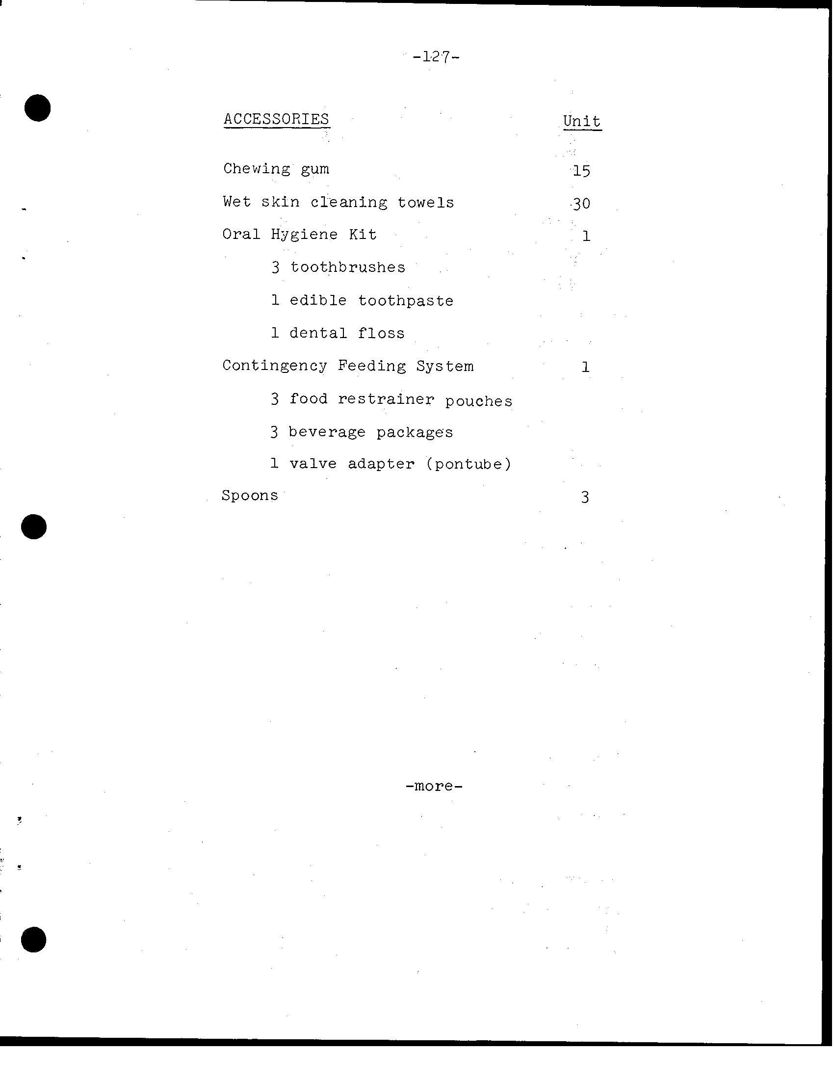
ACCESSORIES Unit Chewing gum 15 Wet s k i n c l e ig towe 30 Hygiene K i t 1 3 toothbrushes e d i b l e t o o t h p a s t e d e n t a l f l o s s Contingency Feeding System 1 3 food r e s t r a i n e r pouches 3 beverage packages valve a d a p t e r (pontube) Spoons 3 a -more- ?
-128- Snack Pantry Breakfast Units Peaches 6 F r u i t Cocktail 6 Canadian Bacon and Applesauce 3 Bacon Squares (8) 1 2 Sausage 3 Sugar Coated Corn Flakes 6 Strawberry Cubes (4) 3 Cinn. T s t d. Bread Cubes (4) 6 Apricot Cubes (4) 3 3 Peanut Cubes (4) 51 Salads/Meats Salmon Salad 3 Tuna Salad 3 Cream of Chicken Soup 6 Shrimp Cocktail 6 Spaghetti and Meat Sauce* 6 Beef Pot Roast 3 Beef and Vegetables 3 Chicken and Rice* 6 Chicken Stew* 3 Beef Stew* 3 Pork and Scalloped Potatoes* 6 Ham and Potatoes (Wet) 3 Turkey and Gravy (Wet) 6 57 *Spoon-Bowl Package -more-
-- -1 7 2 - ~ Snack _Pantr:% 3ehydratable u n i t s I I Sanana h d d i n g I _ 6 Z u t t e r s c o t c h Pudding I 6 Applesauce 1 . I 6 Chocolate Pudding I 24 Beverages Orange Drink 6 Orange-Grapefruit Drink 3 Pineapple-Grapefruit Drink 3 G r a p e f r u i t Drink 3 Grape Drink 6 Grape Punch 3 Cocoa 6 Coffee (B) 15 Coffee (S) 15 Coffee (C and S ) 15 75 -more-
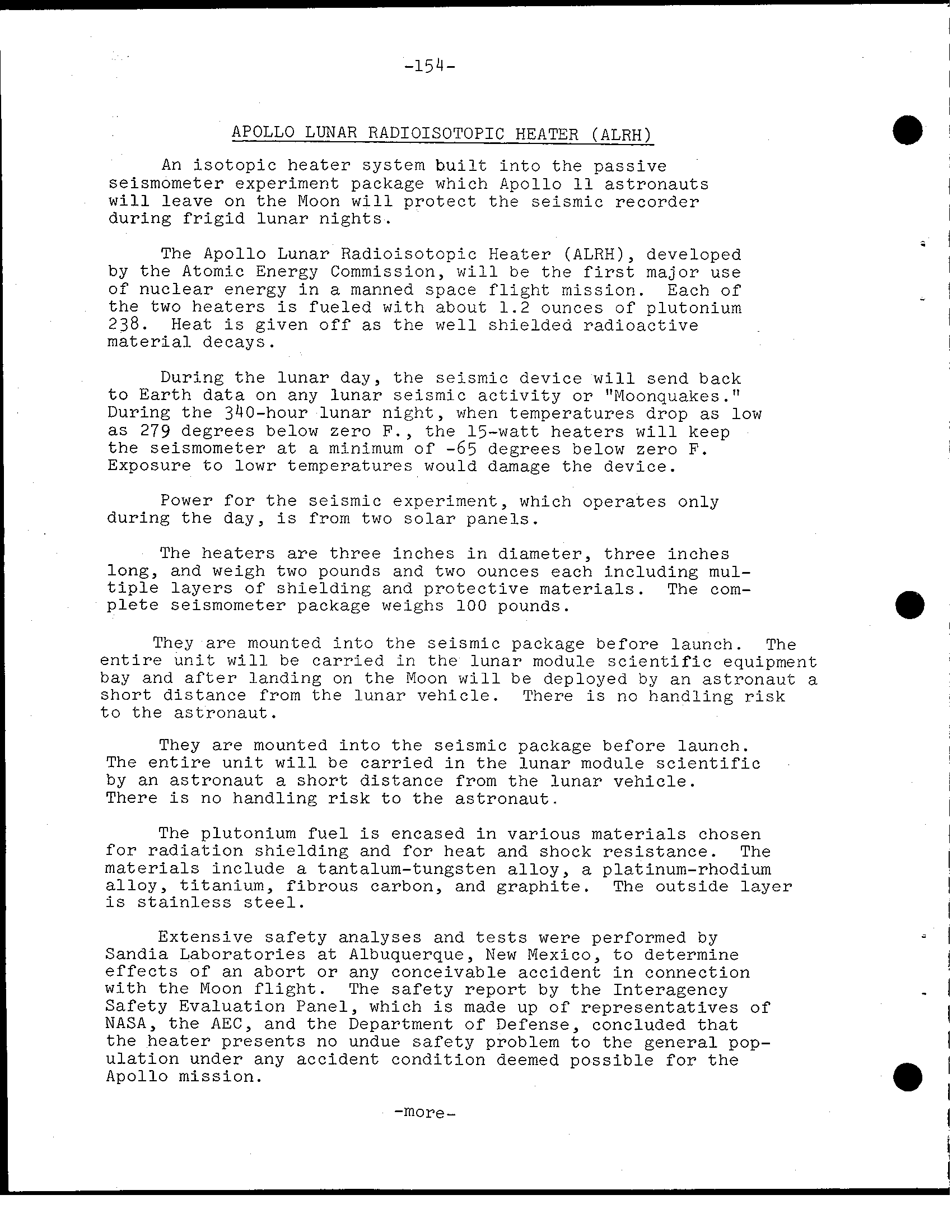
-130- Snack P a n t r y Dried F r u i t s Units stow I I Apricots 6 - I Peaches 6 I 6 1 I I I Sandwich Spread Ham Salad (5 1 1 Tuna Salad (5 oz.) 1 1 Chicken Salad (5 o z.) 1 1 Cheddar Cheese (2 o z.) 3 1 Bread 6 6 RY e White 6 6 -more-
-131- Snack Pantry Bites Units 6 Cheese Cracker Cubes (6) 6 BBQ Beef B i t s (4) 6 Chocolate Cubes (4) 6 Brownies (4) 6 Date Fru itcak e (4) 6 Pineapple Fruitc a k e (4) 6 J e l l i e d F r u i t Candy (4) 6 Candy (4)
-132- Meal A. Bacon Squares(8) Peaches Sugar Cookie Cubes (6) Coffee Pine app - Grape r u i d r i n k Meal B. stew C r e a m of Chicken Soup F r u i t Cake (4) Grape Punch Orange Drink U n i t s E x t r a Beverage 8 Dried F r u i t 4 Candy B a r 4 Bread 2 Ham Salad Spread (t u b e f o o d) Turkey and Gravy 2 Spoons 2 -more-
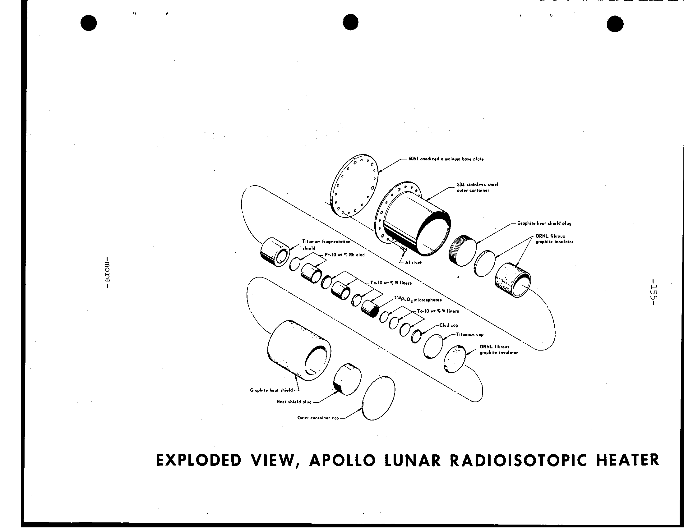
-133- Personal Hygiene Crew personal hygiene equipment aboard Apollo in- cludes body cleanliness items, the waste management system and one medical k i t. Packaged with the food are toothbrush and two-ounce tube of toothpaste for each crewman. Each man-meal package contains a 3.5-by-four-inch wet-wipe cleansing towel. Additionally, three packages of 12-by-12-inch dry towels are stowed beneath the command module p i l o t's couch. Each package contains seven towels. Also stowed under the command module p i l o t's couch are seven tissue dispensers containing 53 three- ply tissues each. Solid body collected i n Gemini-type plastic defecation bags which contain a germicide t o prevent bacteria and gas formation. The bags are sealed a f t e r use and stowed in empty food containers for post-flight analysis. Urine collection devices are provided for use while wearing either the pressure s u i t or the inflight coveralls. urine dumped overboard through urine dump valve in the CW and stored i n the LM. Medical K i t 5x5x8-inch medical accessory k i t I s stowed i n com- partment on spacecraft w a l l the lunar module pilot couch. medical k i t contains three motion sickness injectors, three pain suppression injectors, one two- ounce bottle aid ointment, two one-ounce bottle eye drops, three nasal sprays, two compress bandages, 12 adhesive bandages, one o r a l thermometer and faur spare crew biomedical harnesses. P i l l s i n the medical k i t 60 antibiotic, 12 nausea, 12 stimulant, pain k i l l e r, 60 decongestant, 24 72 aspirin and sleeping. Additionally, small medical k i t containing four s t h u l a n t, eight two sleeping and four pain k i l l e r p i l l s, 12 aspirin, one bottle eye drops and two compress bandages is stowed i n the lunar module f l i g h t compartment. Survival Gear The survival k i t stowed i n two rucksacks i n the right- hand forward equipment bay above the lunar module pilot. Contents of rucksack No. two combination survival lights, one desalter k i t, three sunglasses, one radio beacon, one spare radio beacon battery and spacecraft connector cable, one knife i n three water containers and two con- tainers of Sun lotion. - -more
-13'1- a - -more
-135- Rucksack No. one three-man l i f e with CO inflater, one sea anchor, two dye three gun- bonnets, one mooring lanyard, three manlines, and two attach . brackets The survival k i t designed to provide 48-hour postlanding (water o r land) survival capability for three crewmen between 40 degrees North and South latitudes. Biomedical Inflight Monitoring The Apollo crew biomedical telemetry received by Manned Space Flight Network w i l l relayed for in- stantaneous display Mission Control Center where rate breathing rate w i l l displayed on the surgeon's console. rate and respiration average, range and deviation are computed and displayed on TV screens. In addition, the instantaneous r e a l - t h e and delayed EKG and respiration are recorded on s t r i p charts for each man. Biomedical telemetry w i l l be simultaneous from all crew- men while i n the CSM, but selectable by manual onboard switch i n the LM. Biomedical observed by the flight surgeon and his team i n the L i f e Support Systems Staff Support Room w i l l be correlated with spacecraft and space s u i t environmental displays. Blood pressures no longer telemetered they were i n the Mercury and Gemini programs. O r a l temperatue, how- ever, can be measured onboard for diagnostic purposes and I voiced down by the crew case of inflight illness. - -more a
-136- Training crewmen of Apollo have spent more than five hours of formal crew training f o r each hour of the lunar-orbit mission's eight-day duration. More than 1,000 hours of training were in Apollo crew training syllabus over and above normal preparations for mission--technical briefings and reviews, pilot meetings and study. Apollo 11 crewmen also took i n spacecraft manu- facturing checkouts the North American Rockwell plant in Downey, C a l i f., Grumman Aircraft Engineering Corp., N.Y., and in prelaunch testing at NASA Kennedy Space Center. Taking i n factory and launch area testing provided the crew with thorough operational knowledge of the complex vehicle. of specialized Apollo crew training topics Detailed of on spacecraft systems, operation and modifications. Saturn launch vehicle briefings on countdown, range dynamics, failure modes and abort conditions. launch vehicle briefings were updated periodcally. Apollo Guidance and Navigation system briefings the Massachusetts Institute of Technology Instrumentation Laboratory. * Briefings and continuous training on mission photo- graphic objectives and use of camera equipment. * Extensive pilot participation i n reviews of flight procedures for normal w e l l emergency situations. * Stowage reviews and practice in training sessions i n the spacecraft, mockups and command module simulators allowed crewmen to evaluate spacecraft stowage of crew-associated equipment. * More than 400 hours of training per man i n command module and lunar module simulators MSC and KSC, including closed- loop simulations with flight controllers i n the Mission Control Center. Other Apollo various locations used extensiyely for specialized crew training. * Entry corridor deceleration profiles lunar-return conditions i n MSC Flight Acceleration Facility manned centrifuge. a -more-
Lunar surface and 1-g walk-throughs of lunar surface EVA operations covering lunar geology and microbiology and dep N loyment of experiments i n the Early Apollo Surface Experiml ent Package (EASEP). Training i n lunar surface EVA included practice sessions with lunar surface sample tools a nd return containers, cameras, erectable S-band antenna and the modular equipment stowage assembly (MESA) housed i n LM descent stage. Proficiency flights i n lunar landing vehicle (LLTV) for commander. * Zero-g aircraft flights using command module and lunar module mockups for EVA and pressure doffing/donning practice and training. * Underwater zero-g i n the MSC Water Immersion Facility using spacecraft mockups t o further familiarize crew with a l l aspects of CSM-LM docking tunnel intravehlcular transfer and EVA i n pressurized * Water conducted i n indoor tanks w e l l i n Gulf of Mexico Included uprighting from I1 position (apex down) t o position (apex up), onto and helicopter pi'ckup. a * Launch training f r o m mockups and from the actual spacecraft on launch pad for possible emergencies such contaminants and power failures. * The training covered use of Apollo spacecraft suppression equipment i n the cockpit. * Planetarium reviews Morehead Planetarium, Chapel H i l l, N.C., and at Griffith Planetarium, Los of celestial with special on 37 navigational used the Apollo guidance computer. -more-
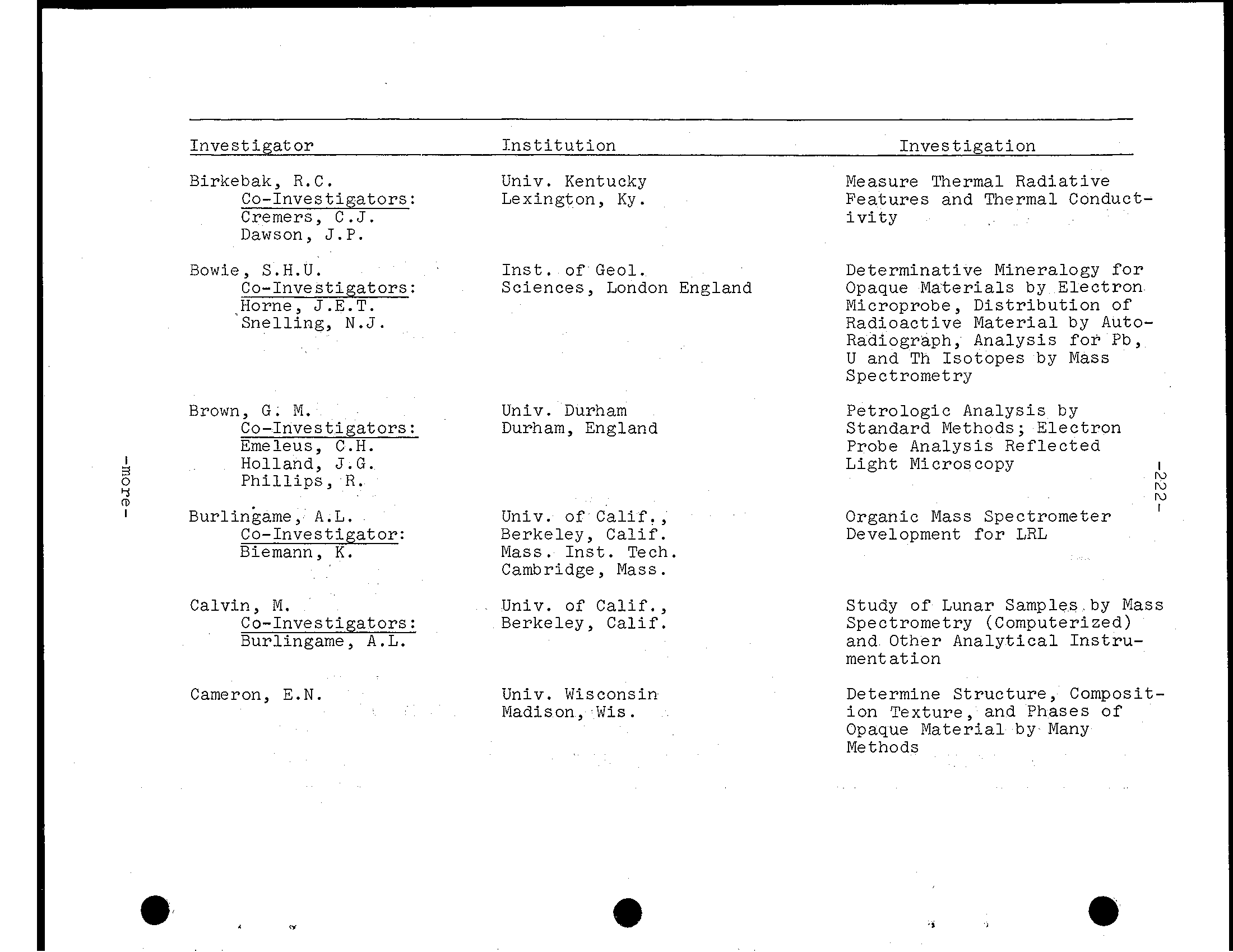
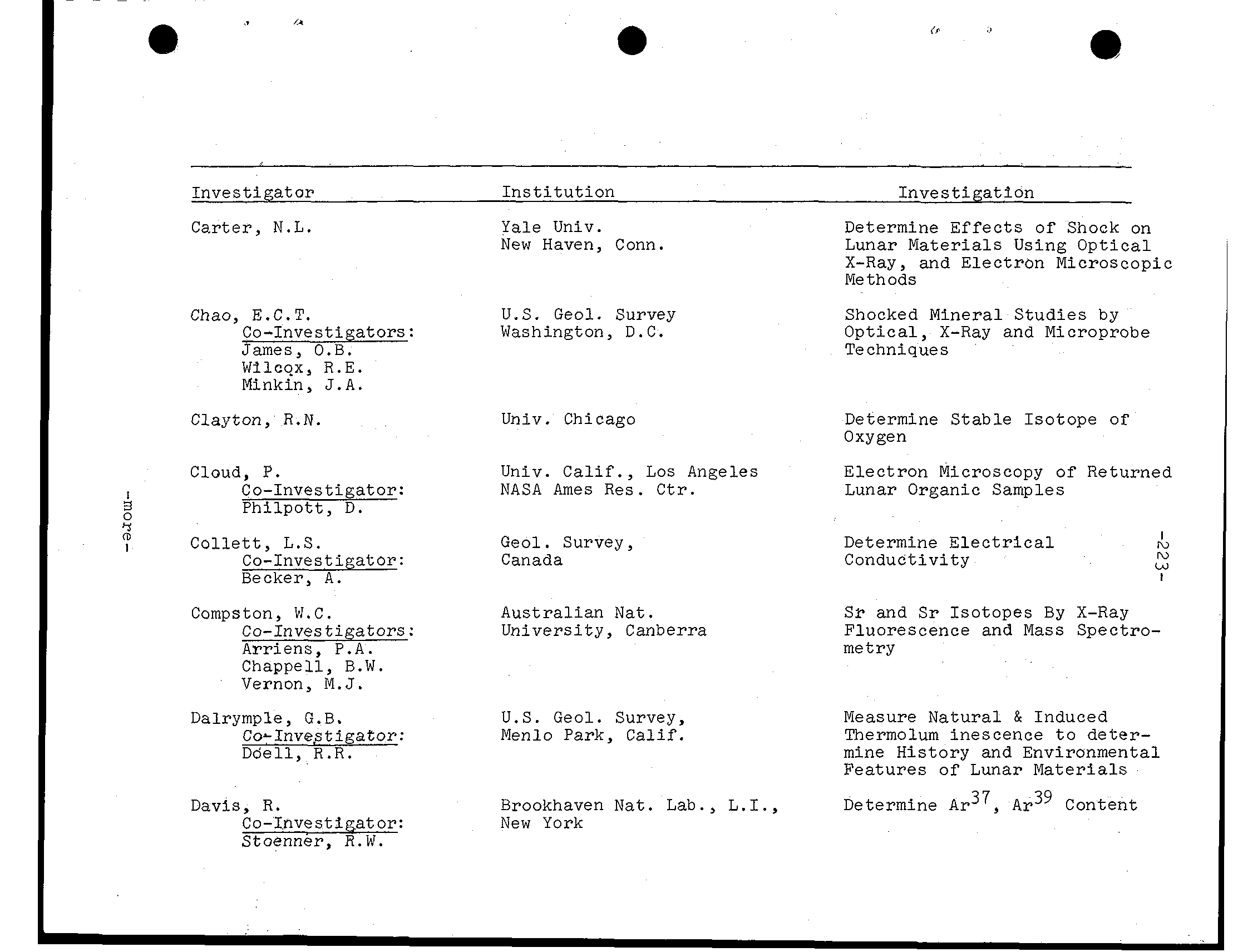
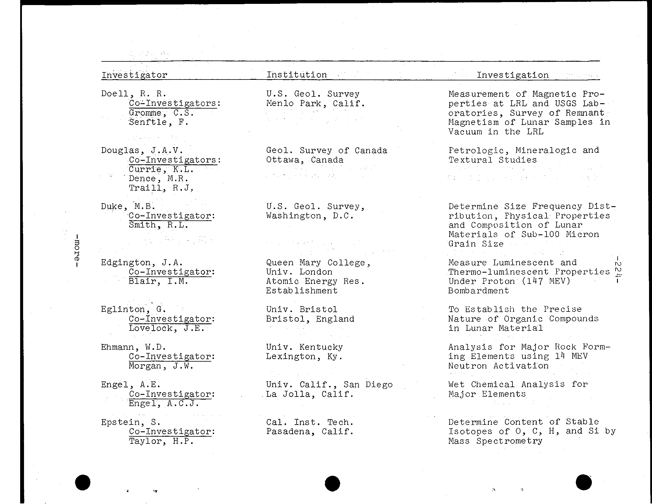
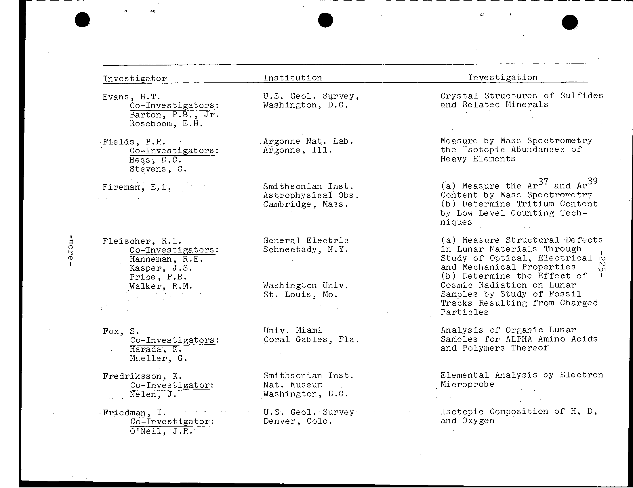
-138- NATIONAL AERONAUTICS AND SPACE ADMINISTRATION WASHINGTON, D. C. 20546 BIOGRAPHICAL DATA NAME: N e i l A. Armstrong ( Mr.) NASA Astronaut, Commander, Apollo BIRTHPLACE AND DATE: Born in Wapakoneta, Ohio, on August 5, 1930; is the son of M r. and Stephen Amstrong of Wapakoneta. PHYSICAL DESCRIPTION: Blond blue eyes; height: 5 inches; weight 165 pounds. EDUCATION: Attended secondary school i n Wapakoneta, Ohio; received Bachelor of Science i n Peronautical Engineering from Purdue University i n 1955. Graduate - School University of Southern California. MARITAL STATUS: t o the former Janet Shearon Evanston, Illinois, who daughterof Louise Shearon California. CHILDREN: June 30, 1957; Mark, April 8, 1963. OTHER ACTIVITIES: hobbies include soaring (for which he Federation Aeronautique Internationale gold holder). ORGANIZATIONS: Associate Fellow of the Society of Experimental Test Pilots; fellow of the American Institute of Aeronautics and Astronautics; and member the Soaring Society of SPECIAL HONORS: ReciDient of the 1962 Institute of Aerospace Sciences Octave Chanute Award; the 1966 A I A A Astronautics NASA Exceptional Service and t h e 1962 John Montgomery Award. EXPERIENCE: Armstrong was naval aviator from 1949 t o 1952 and 78 combat missions during the Korean action. He joined N A S A's L e w i s Research Center i n 1955 (then NACA L e w i s Flight Propulsion Laboratory) and transferred - ; t o NASA High Speed Flight Station (now Flight Research Edwards A i r Force California, an I aeronautical research p i l o t f o r NACA and NASA. In t h i s I capacity, he performed an X-15 project pilot, , that t o over and approximately 4,000 m i l e s hour. ~ l -more-
-139- Other f l i g h t test work included p i l o t i n the X - 1 rocket 8 airplane, the F-100, F-101, F-102, F-10 E D, B-47, t h e paraglider, and others. A s p i l o t of t h e B-29 "drop"a i r c r a f t, he participated i n the launches of over rocket airplane f l i g h t s. He has logged more than 4,000 hours flying CURRENT ASSIGNMENT: Mr. Armstrong was selected an astronaut ~y NASA i n September 1962. served backup command p i l o t f o r t h e Gemini 5 f l i g h t. A s command p i l o t for theGemini 8 mission, whlch was launched on March 16, 1966, performed the successful dock- ing of two vehicles i n space. Theflight, Originally scheduled t o days, was terminated e a r l y due t o malfunctioning OAMS thruster; but t h e demonstrated exceptional p i l o t i n g s k i l l i n overcoming t h i s problem and bringing t h e spacecraft t o landing. subsequently served backup command p i l o t for Gemini mission and currently assigned as commander f o r Apollo mission, and will probably be human t o foot on t h e Moon. A s c i v i l servant, Armstrong, a GS-16 Step 7, earns $30,054 per annum -more- June 1969
-140- NATIONAL AERONAUTICS AND SPACE ADMINISTRATION WASHINGTON, C. 20546 BIOGRAPHICAL DATA NAME: Michael Collins (Lieutenant Colonel, USAF) NASA Astronaut, Command Module Pilot, Apollo BIRTHPLACE AND DATE: Born i n Rome, Italy, on October 31, 1930. His mother, James L. Collins, resides i n Washington, D. C. PHYSICAL DESCRIPTION: Brown brown eyes; neight: 5 inches; weight: 165 pounds. EDUCATION: Graduated from Saint Albans School i n Washington, D.C.; received Bachelor of Science degree from the United States Military Academy West Point, New York, i n 1952. MARITAL STATUS: Married to the M. Finnegan of Boston, Massachusetts. CHILDREN: Kathleen, 6,. 1959; Ann S., October 1961; Michael L., February 23, 1963. OTHER ACTIVITIES: H i s hobbies include fishing and handball. ORGANIZATIONS: Member of the Society of Experimental T e s t Pilots. SPECIAL HONORS: Awarded NASA Exceptional Service Medal, the A i r Force Command Pilot Astronaut Wings, and the A i r Force Distinguished Flying I I EXPERIENCE: Collins, an A i r Force L t Colonel, chose an A i r Force career following graduation from Point. I 1 He served an experimental f l i g h t officer the A i r Force Flight Teat Center, Edwards A i r Force California, 1 and, i n t h a t capacity, tested performance and s t a b i l i t y and control characteristics of A i r Force aircraft--primarily fighters. He has logged more than 4,000 hours flying time, including more than hours i n jet a i r c r a f t. m -more-
-141- CURRENT ASSIGhPlENT: Lt. Colonel Collins one of the t h i r d e group of astronauts named by NASA i n October 1963. He since served backup p i l o t for Gemini 7 mission. A s p i l o t on the 3-day 44-revolution Gemini mission, launched J u l y 18, 1966, Collins with command p i l o t John Young i n accomplishments of that record- s e t t i n g f l i g h t. These accomplishments include success- f u l rendezvom and docking with a separately launched Agena target venicle and, u s i n g power of Agena, maneuvering Gemini spacecraft i n t o another o r b i t f o r rendezvous with second, passive Agena. Collins' ful performance i n completing two periods of extravehicular activity, including h i s recovery of micrometeorite detection experiment from passive Agena, added greatly t o our knowledge of manned space flight. Gemini attained an apogee of approximately 475 miles and traveled distance of 1,275,091 s t a t u t e miles-- which splashdown occurred i n the Atlantic 529 s t a t u t e miles of Cape Kennedy. The spacecraft landed 2.6 from the USS GUADALCANAL and the second i n Gemini program t o land within and range of prime recovery vessel. H e currently assigned command module p i l o t on Apollo mission. The annual pay and allowances of an A i r Force lieutenant colonel w i t h Collins' time i n service t o t a l s $17,147.36. -more- June 1969
-142- N A T I O N A L A E R O N A U T I C S A N D SPACE A D M I N I S T R A T I O N WASHINGTON, D. C. 20546 B I O G R A P H I C A L D A T A NAME: Edwin E. Aldrin, (Colonel, USAF) NASA Astronaut, Lunar Module Pilot, Apollo 11 BIRTHPLACE AND DATE: Born i n Montclair, New Jersey, on January 1930, and is the son of the Marion Moon Aldrin and Colonel (USAF Retired) Edwin E. Aldrin, who i n B r i e l l e, New Jersey. PHYSICAL DESCRIPTION: Blond hair; blue eyes; 5 inches; weight: pounds. EDUCATION: Graduated from Montclair High School, Montclair, N e w Jersey; received Bachelor of Science degree from United States Point, New York, i n 1951 and Doctor of Science degree i n Astronautics from the Massachusetts I n s t i t u t e of Technology i n 1963; * recipient of an Honorary Doctorate of Science Gustavus Adolphus College i n 1967, Honorary degree from University, MARITAL STATUS: Married t o the formerJoan A. Archer of Ho-Ho-Kus, New Jersey, whose parents, M r. and M r s. Archer, residents of t h a t city. CHILDREN: Michael, September 1955; Janice R., August 16, 1957; Andrew June 17, 1958. OTHER ACTIVITIES: He is Scout Badge Counsellor and an E l d e r and of Presbyterian Church. His hobbles include running, scuba diving, and high exercises. ORGANIZATIONS: Fellow of American I n s t i t u t e of Aeronautics and Astronautics; member of Society of Experimental T e s t P i l o t s, Sigma Gamma Tau (aeronautical engineering society), Tau P i (national engineering society), and Sigma X i (national science researchsociety); and 32nd Degree Mason advanced through Commandery and Shrine. a
-143- SPECIAL HONORS: Awarded the Distinguished Flying Cross with one OakLeaf Cluster, the A i r Medal with two O a k Clusters, the A i r Force Commendation Medal, the NASA Exceptional Service and A i r Force Command P i l o t Astronaut Wings, the NASA Group Achievement Award f o r Rendezvous Operations Planning Team, an Honorary L i f e Membership i n Inter- national Association of Machinists and Aerospace Workers, and an Honorary Membership i n Aerospace Medical Association. EXPERIENCE: Aldrin, an A i r Force Colonel, was graduated i n c l a s s of 475 from t h e United States Military Academy Point i n 1951 and subsequently received h i s wings Bryan, Texas, i n 1952. He flew 66 combat missions i n F-86 a i r c r a f t while on duty i n Korea with t h e 51st Fighter Interceptor Wing and credited with destroying two M I G - 1 5 A t Nellis A i r Force Nevada, he served as a n aerial gunnery instructor and then attended the Squadron Officers’ School A i r University, Maxwell A i r Force Alabama. Following h i s assignment Aide t o Dean of Faculty t h e United A i r Force Aldrin Flew F-100 f l i g h t commander with 36th Wing Bitburg, He attended MIT, receiving doctorate completing h i s concern- ing guidance for manned o r b i t a l rendezvous, and then assigned t o Gemini Target Office of A i r Force Space Systems Division, H e w a s transferred t o the U S A F Office t h e Manned c r a f t Center whLch responsible for integrating DOD experiments i n t o t h e NASA Gemini f l i g h t s. He logged approximately 3,500 hours flying including 2,853 hours i n jet a i r c r a f t and 139 hours i n helicopters. has made several i n t h e lunar landing research vehicle. CURRENT ASSIGNMENT: Colonel Aldrin was one of the t h i r d group of astronauts named by NASA i n October 1963. He since served backup p i l o t for the Gemini 9 mission and prime p i l o t for Gemini mission. -more-
-144- On November 1966, he and command p i l o t Love11 were launched i n t o space i n Gemini spacecraft on 4-day 59-revolution which brought Gemini Program t o successful close. Aldrin new record for extravehicular a c t i v i t y (EVA) by accruing slightly more than 53 hours outside spacecraft. During the umbilical EVA, attached tether t o the Agena; retrieved experiment package from the spacecraft; and evaluated use body r e s t r a i n t s specially designed f o r completing work tasks outside t h e spacecraft. He completed numerous photographic experiments and obtained pictures taken from space of an eclipse of sun. major accomplishments of the +hour 35-minute f l i g h t included third-revolution rendezvous with t h e previously Agena, using for backup onboard computations due t o failure, and f u l l y automatic controlled reentry of spacecraft. Gemini down i n within 2$ m i l e s of recovery ship USS WASP. Aldrin currently assigned lunar module f o r Apollo annual and allowances of an A i r colonel w i t h Aldrin's t i m e i n service t o t a l $18,622.56. -more- June 1969
-145- I. EARLY APOLLO SCIENTIFIC EXPERIMENTS PACKAGE (EASEP) The Apollo 11 scientific experiments for deployment on the lunar surface near the touchdown point of the lunar module are stowed in the LM's scientific equipment bay at the left rear quadrant of the descent stage looking for- ward. The Early Apollo Scientific Experiments Package (EASEP) will be carried only on Apollo 11; subsequent Apollo lunar landing missions will carry the more comprehensive Apollo Lunar Surface Experiment Package (ALSEP). EASEP consists of two basic experiments: the passive seismic experiments package (PSEP) and the laser ranging retro-reflector (LRRR). Both experiments are independent, self-contained packages that weigh a total of about 170 pounds and occupy 12 cubic feet of space. PSEP uses three long-period seismometers and one short- period vertical seismometer for measuring meteoroid impacts and moonquakes. Such data will be useful in determining the interior structure of the Moon; for example, does the Moon have a core and mantle like Earth. The seismic experiment package has four basic subsystems: structure/thermal subsystem for shock, vibration and thermal protection; electrical power subsystem generates 3'1 to 46 watts by solar panel array; data subsystem receives and decodes MSFN uplink commands and downlinks experiment data, handles power switching tasks; passive seismic experiment subsystem measures lunar seismic activity with long-period and short- period seismometers which detect inertial mass displacement. The laser ranging retro-reflector experiment is a retro- reflector array with a folding support structure for aiming and aligning the array toward Earth. The array is built of cubes of fused silica. Laser ranging beams from Earth will be reflected back to their point of origin for precise mea- surement of Earth-Moon distances, motion of the Moon's center of mass, lunar radius and Earth geophysical information. Earth stations which will beam lasers to the LRRR in- clude the McDonald Observatory at Ft. Davis, Tex.; Lick Obser- vatory, Mt. Hamilton, Calif.; and the Catalina Station of the University of Arizona. Scientists in other countries also plan to bounce laser beams off the LRRR. Principal investigators for these experiments are Dr. C. Alley, University of Maryland (Laser Ranging Retro Feflector) and Dr. Garry Latham, Lamont Geological Observatory (Passive Seismic Experiments Package). -more-
EASEPILM INTERFACE LM CENTER1 I NE FWD a 2
EASEP DEPLOYMENT ZONES I ZONE DEPLOYMENT OF EASEP RESTRICTED BY THERMAL RADIATION FROM THE L M II ZONE SIGNIFICANT AERODYNAMIC HEATING FROM L M ASCENT ENGINE PLUME ZONE POSSIELE CONTAMINATION BY KAPTON AND INCONEL DEBRIS Isz: ZONE DESIRABLE DEPLOYMENT ZONES (AVOID L M SHADOW)
PSEP STOWED CONFIGURATION SOLAR PANEL SEISMIC PASSIVE EXPER I MENT PACKAGE
PSEP DEPLOYED CONFIGURATION
LASER RANGING RETRO-REFLECTOR EXPERIMENT NGLE INDICATING RETRO-REFLECTOR BOOM AlTAC HMENT iD A1 GNMENT HANDLE ASSY
a LRRR DETAILS RETRO-REFLECTOR ARRAY A IM-ANGLE BRACKET REAR SUP BOOM ATTACHMENT IM-ANGLE HANDLE ALIGNMENT HANDLE r R E T A N ER R N G SIMPLIFIED TYPICAL LASER RAY PATH (ALUM1N UM) FRONT VIEW
-152- SOLAR WIND EXPERIMENT -more-
COMMAND AND TELEMETRY LINKS TELEMETRY LINK COMMAND LINK COMMANDS POWER
-154- APOLLO LUNAR RADIOISOTOPIC HEATER (ALRH) An isotopic heater system built into the passive seismometer experiment package which Apollo 11 astronauts will leave on the Moon will protect the seismic recorder during frigid lunar nights. The Apollo Lunar Radioisotopic Heater (ALRH), developed by the Atomic Energy Commission, will be the first major use of nuclear energy in a manned space flight mission. Each of the two heaters is fueled with about 1.2 ounces of plutonium 238. Heat is given o f f as the well shielded radioactive material decays. During the lunar day, the seismic device will send back to Earth data on any lunar seismic activity or "Moonquakes." During the 3hO-hour lunar night, when temperatures drop as low as 279 degrees below zero F., the 15-watt heaters will keep the seismometer at a minimum of -65 degrees below zero F. Exposure to lowr temperatures would damage the device. Power for the seismic experiment, which operates on11 during the day, is from two solar panels. The heaters are three inches in diameter, three inches long, and weigh two pounds and two ounces each including mul- tiple layers of shielding and protective materials. The com- plete seismometer package weighs 100 pounds. They are mounted into the seismic package before launch. The entire unit will be carried in the lunar module scientific equipment bay and after landing on the Moon will be deployed by an astronaut a short distance from the lunar vehicle. There is no handling risk to the astronaut. They are mounted into the seismic package before launch. The entire unit will be carried in the lunar module scientific by an astronaut a short distance from the lunar vehicle. There is no handling risk to the astronaut. The plutonium fuel is encased in various materials chosen for radiation shielding and for heat and shock resistance. The materials include a tantalum-tungsten alloy, a platinum-rhodium alloy, titanium, fibrous carbon, and graphite. The outside layer is stainless steel. Extensive safety analyses and tests were performed by Sandia Laboratories at Albuquerque, New Mexico, to determine effects an abort or any conceivable accident in connection with the Moon flight. The safety report by the Interagency Safety Evaluation Panel, which is made up of representatives of NASA, the AEC, and the Department of Defense, concluded that the heater presents no undue safety problem to the general pop- ulation under any accident condition deemed possible for the Apollo mission. -more-
a EXPLODED VIEW, APOLLO LUNAR RADIOISOTOPIC HEATER
Fragmentation shield Graphite ablative heat shield osrcmbly Outer contoincr assembly Outer liner assembly Base plotc Inner liner assembly Rivet, solid m i v o ~ s dh eed THE APOLLO LUNAR RADIOISOTOPIC HEATER * a
-157- E Sandia Laboratories operated f o r the AEC by Western E l e c t r i c Company- The heater was fabricated by AEC's Mound Laboratory at Miamisburg, Ohio, which operated by Monsanto Research Corporation. The major use of nuclear energy i n space came i n ' 5 . 1 9 6 1 with the launching of navigation s a t e l l i t e with an i s o t o p i c generator. Plutonium 238 f u e l s the device which operating. Two similar u n i t s were launched i n 1961 and two more i n 1963. April, NASA launched Nimbus weather s a t e l l i t e with 2-unit nuclear isotopic system f o r senerating e l e c t r i - c a l power. The Systems f o r Nuclear Auxiliary Power (SNAP-19) generator, developed by AEC, provides supplementary power. Apollo 1 2 scheduled t o carry SNAP-27 radioisotope thermoelectric generator, a l s o developed by AEC, to provide power t o operate the Apollo Lunar Surface Experiments Package (ALSEP). The SNAP-27 also contains plutonium 238 the heat source. Thermoelectric elements convert t h i s heat d i r e c t l y i n t o elec- t r i c a l energy. -more-
-158- APOLLO LAUNCH OPERATIONS Prelaunch Preparations NASA's John F. Kennedy Space Center performs p r e f l i g h t checkout, test and launch o f the Apollo space vehicle. < ' A government-industry team of about 500 w i l l conduct the f i n a l countdown from F i r i n g Room the Launch Control Center (L C C). The f i r i n g room team backed up by more than 5,000 persons who d i r e c t l y involved i n launch operations a t KSC from the t i m e t h e vehicle and spacecraft s t a g e s a r r i v e the Center u n t i l t h e launch completed. I n i t i a l checkout of the Apollo spacecraft conducted i n work stands and i n the a l t i t u d e chambers i n t h e Manned Spacecraft Operations Building (MSOB) Kennedy Space Center. A f t e r completion of checkout spacecraft taken t o the Vehicle Assembly Building (VAB) and mated w i t h t h e launch vehicle. There the f i r s t i n t e g r a t e d spacecraft and launch vehicle conducted. The assembled space vehicle then r o l l e d out t o t h e launch pad f o r f i n a l preparations and countdown t o launch. I n e a r l y January, 1969, f l i g h t hardware for Apollo began a r r i v i n g Kennedy Space Center, j u s t Apollo 9 and Apollo 1 0 were undergoing checkout KSC. The l u n a r module was the piece of Apollo f l i g h t hardware t o a r r i v e KSC. The two stages o f the LM were moved i n t o t h e a l t i t u d e chamber i n the Manned Spacecraft Operations Building an i n i t i a l receiving inspection i n January. I n the chamber the LM underwent systems and both unmanned and manned chamber runs. During these runs t h e chamber was pumped out t o simulate the vacuum of space a t a l t i t u d e s i n excess of 200,000 There the spacecraft systems and t h e a s t r o n a u t s' support systems were t e s t e d. LM w a s undergoing preparation f o r manned a l t i t u d e chamber runs, the Apollo command/service module a r r i v e d KSC and receiving inspection, too, was placed i n an a l t i t u d e chamber i n t h e MSOB for systems and unmanned and manned chamber The prime and backup crews p a r t i c i p a t e d i n the chamber runs on both LM and the CSN. I n e a r l y April, the LM and CSM were removed from the chambers. After i n s t a l l i n g the landing gear on t h e LM and t h e SPS engine nozzle on the CSM, LM was encapsulated i n t h e spacecraft LM adapter (SLA) and the CSM mated to the SLA. On April 1 4, the assembled spacecraft w a s moved t o t h e VAB where was mated t o t h e launch vehicle. -more-
-159- The launch v e h i c l e f l i g h t hardware began a r r i v i n g at KSC i n mid-January and by March 5 t h e t h r e e s t a g e s and t h e instrument u n i t were e r e c t e d on Mobile Launcher i n high bay Tests were conducted on i n d i v i d u a l systems on each of t h e s t a g e s and on t h e o v e r a l l launch vehicle before t h e s p a c e c r a f t was e r e c t e d atop t h e v e h i c l e. After s p a c e c r a f t e r e c t i o n, t h e s p a c e c r a f t and launch vehicle e l e c t r i c a l l y mated and t h e o v e r a l l t e s t (plugs-in) of t h e space v e h i c l e was conducted. I n accordance with t h e philosophy of accomplishing much o f t h e checkout p o s s i b l e i n t h e VAB, the o v e r a l l test was conducted before t h e space v e h i c l e was moved t o t h e launch pad. The plugs-in test v e r i f i e d t h e c o m p a t i b i l i t y of t h e space vehicle systems, ground support equipment and o f f - s i t e support f a c i l i t i e s by demonstrating t h e a b i l i t y of t h e systems t o proceed through simulated countdown, launch and f l i g h t. During t h e simulated f l i g h t p o r t i o n of t h e the systems were required t o respond to both emergency and normal f l i g h t conditions. The move to Pad A from t h e VAB on May 2 1 occurred while Apollo 1 0 enroute t o Moon for r e h e a r s a l of l u n a r landing mission and test of complete s p a c e c r a f t i n t h e near-lunar environment. a Apollo w i l l mark launch Pad A on Complex 39. The two unmanned Saturn V launches and t h e manned Apollo 8 and 9 launches took place Pad A. Apollo 1 0 was t h e only launch t o from Pad B. The space v e h i c l e F l i g h t Readiness T e s t was conducted June 4-6. Both t h e prime and backup crews p a r t i c i p a t e i n p o r t i o n s of t h e FRT, which f i n a l o v e r a l l t e s t of t h e space v e h i c l e systems and ground support equipment when a l l systems are n e a r p o s s i b l e t o launch configuration. After hypergolic f u e l s were loaded aboard t h e space v e h i c l e and t h e launch v e h i c l e f u e l (RP-1) was brought aboard, f i n a l major test of t h e space vehicle began. T h i s countdown demonstration test (CDDT), for t h e f i n a l countdown to launch. The CDDT f o r Apollo divided i n t o a "w e t" and "dry" p o r t i o n. During the. o r "wet" p o r t i o n, t h e e n t i r e countdown, i n c l u d i n g p r o p e l l a n t loading, w a s c a r r i e d o u t down to T-8.9 seconds, t i m e for i g n i t i o n sequence The a s t r o n a u t crew d i d n o t p a r t i c i p a t e i n t h e wet CDDT. -more-
-160- A t t h e completion of t h e wet CDDT, t h e cryogenic pro- p e l l a n t s (l i q u i d oxygen and l i q u i d hydrogen) were off-loaded, and f i n a l p o r t i o n of t h e countdown was t h i s time s i m u l a t i n g t h e f u e l i n g and with t h e prime astronaut crew p a r t i c i p a t i n g they w i l l on launch day. By t h e time Apollo was e n t e r i n g t h e f i n a l phase of checkout procedure Complex 39A, crews had a l r e a d y s t a r t e d t h e checkout of Apollo 1 2 and Apollo 13. The Apollo 1 2 space- craft completed a l t i t u d e chamber t e s t i n g i n June and was l a t e r mated t o t h e launch v e h i c l e i n t h e VAB. Apollo 1 3 f l i g h t hard- ware began a r r i v i n g i n June t o undergo preliminary checkout. Because of t h e complexity involved i n t h e checkout of t h e 363-foot-tall (110.6 meters) Apollo/Saturn V c o n f i g u r a t i o n, t h e launch teams make use of e x t e n s i v e automation i n t h e i r checkout. Automation one of t h e major d i f f e r e n c e s i n checkout used i n Apollo compared to t h e procedures used i n t h e Mercury and Gemini programs. Computers, d a t a d i s p l a y equipment and tech- niques used throughout automatic checkout from t h e t i m e t h e launch v e h i c l e e r e c t e d i n t h e VAB through l i f t o f f. A b u t separate computer o p e r a t i o n c a l l e d ACE (Acceptance Checkout-Xquipment) used t o v e r i f y t h e f l i g h t r e a d i n e s s of t h e s p a c e c r a f t. Spacecraft checkout c o n t r o l l e d from s e p a r a t e rooms i n Manned S p a c e c r a f t Operations Building. -more- -
-161- LAUNCH COMPLEX 39 Launch Complex 39 f a c i l i t i e s the Kennedy Space Center were planned and b u i l t specifically for the Ap0110 Saturn V, space vehicle will be used t o carry astronauts t o the Moon. Complex 39 introduced the mobile concept of launch operations, departure from the fixed launch techniques used previously Cape Kennedy and other launch Since the 1950's when the b a l l i s t i c were launched, fixed launch concept had been used on NASA missions. method called f o r assembly, checkout and launch of a rocket one launch In addition t o tying up this method also often the flight equipment exposed t o the outside influences of the weather for extended periods. U s i n g the mobile concept, the space vehicle thoroughly checked i n an enclosed building before moved t o the launch for f i n a l preparations. This affords greater protection, a more systematic checkout process using computer techniques and high launch f o r the future, since the minimal. Saturn V shipped t o the Kennedy Space Center by ocean-going vessels and specially designed such the Guppy. Apollo spacecraft modules transported by air. a spacecraft components taken t o the Manned Spacecraft Operations Building for preliminary checkout. The Saturn V brought t o the Vehicle Assembly Building arrival the nearby turning basin. The major components of Complex 39 include: Vehicle Assembly Building (VAB) where the Apollo was and prepared; Launch Control Center, launch team conducts the preliminary checkout and f i n a l countdown; (3) the mobile launcher, upon which the Apollo was erected for checkout and from where will launched; (4) moblle service structure, which provides external access t o the space vehicle the pad; (5) transporter, which carries the space vehicle and mobile launcher, well as mobile service structure t o the pad; (6) the crawlerway over which the space vehicle travels from the VAB t o the launch pad; and (7) the launch pad i t s e l f. -more-
I I -162- Vehicle Assembly e Vehicle Assembly Building of Launch Cmpbx 39. Covering acres, where the 363-foot-tall space vehicle assembled and tested. The VAB contains 129,482,000 cubic of space, 716 feet long, and 518 and covers 343,500 square feet of floor space. foundation the VAB on 4,225 pilings, each 16 inches i n diameter, driven from 150 t o 170 feet to rock. If placed end t o end, these pilings would extend a distance of 123 miles. The structure of building contains approximately tons of structural The exterior covered by more than million square of insulated aluminum siding. building is divided into a high bay 525 high and low bay high, with both serviced transfer for movement of vehicle low bay work approximately 442 and 274 long, contains eight stage-preparation and checkout cells. These cells are equipped with systems t o simulate interface and operation with other stages and the instrument unit of the c Saturn V launch vehicle. the Apollo 11 launch vehicle upper arrived at Kennedy Space Center, they were moved t o low bay of the VAB. Here, the second and third stages underwent acceptance and checkout testing prior t o mating wlth S-IC atop the Mobile Launcher i n the Ngh area. The high bay provides for and checkout of both the launch vehicle and spacecraft. contains four for vertical assembly and checkout. A t present, three equipped, and the fourth w i l l reserved for possible changes i n vehicle configuration. -- -- Work platforms some three-story buildings i n the high provide access by surrounding the vehicle varying levels. Each high bay five platforms. Each platform consists of two bi-parting sections that move i n from opposite and providing a 360-degree access t o section of the vehicle being checked. A 10,000-ton-capacity conditioning system, sufficient t o cool about homes, helps t o control the environment within the entire office, laboratory, and workshop complex located inside the low bay area of A i r conditioning also fed t o individual platform levels located around the vehicle. a -more-
-163- There 141 lifting devices i n the VAB, ranging from one- ton hoists t o two 250-ton high-lift bridge cranes. The mobile launchers, carried by transporter vehicles, move i n and out of t h e VAB through four doors i n the high bay one i n each of the bays. Each door is shaped an inverted T. They 152 wide and 114 high the narrowing t o 76 i n width. Total door height 456 The lower section of each door is of the aircraft hangar type horizontally on tracks. Above seven telescop- ing vertical panels stacked one above the other, each 50 feet high and driven by an individual motor. Each panel over t h e next to create an opening enough t o permit passage of the mobile launcher. Launch Control Center Adjacent t o the VAB the Launch Control Center (LCC). This four-story structure radical departure from the blockhouses other launch electronic"brain"of Launch Complex 39, LCC was used for checkout and operations Apollo was inside the VAB. The LCC contains display, monitoring, and control equipment used for both checkout and launch operations. The building has checkout stations on second floor, and four rooms, one for each high of VAB, on third floor. Three firing rooms contain identical of control and monitoring equipment, so launch vehicle and checkout of others simultaneously. A ground computer facility associated with each firing room. The computer link provided between LCC and the mobile launcher for checkout of the launch vehicle. T h i s link can be connected t o mobile launcher the VAB or The three equipped firing rooms have 450 consoles which contain controls and displays required for checkout process. digital connecting with the high bay of the VAB and launch carry vast amounts of required during checkout and launch. There are 15 systems i n each LCC firing room, with each of providing digital information instantane- ously. -more-
164- Sixty television cameras positioned around the Apollo/ Saturn V transmitting pictures on modulated channels. The LCC room also contains operational intercommunication channels used by the crews i n the checkout and launch countdown. Mobile Launcher The mobile launcher transportable launch and umbilical tower for space vehicle. Three mobile launchers are used at Complex 39. launcher I s a two-story structure, 25 feet high, 160 feet long, and 135 feet wide. positioned on s i x steel pedestals 22 feet high when i n the VAB or the launch pad. A t launch I n addition to the six steel pedestals, four exten- columns also used t o stiffen the mobile launcher against rebound loads, the Saturn engines cut off. The umbilical tower, extending 398 feet above the launch plat- form, mounted on one end of the launcher base. A hammerhead crane the top a hook height of 376 above the deck with traverse radius of 85 feet from the center of the tower. 12-million-pound mobile launcher stands 445 when resting on The covering about half an compartmented structure built of 25-foot steel girders. launch vehicle over 45-foot-square opening which allows an outlet for engine exhausts into the launch pad trench containing a deflector. This opening lined with placeable independent of the structure, and cooled by curtain initiated two seconds liftoff. nine hydraulically-operated service on the umbilical tower. service support lines for the vehicle umbilical systems and provide access for personnel t o the well astronaut crew t o the spacecraft. On Apollo one of the service retracted i n count. The Apollo spacecraft access arm tracted T-43 minutes. A third service released T-30 seconds, and a fourth about T-16.5 seconds. remaining f i v e arms t o back at vehicle motion T-0. service equipped with a backup retraction system * i n mode fails. -more-
The Apollo access arm (service arm 9), located the 320- foot level above the launcher base, provides access t o the space- craft cabin for the closeout team and astronaut crews. The crew w i l l board the spacecraft about T-2 hours, 40 minutes i n the count. access arm w i l l moved t o parked position, degrees from spacecraft, about T-43 minutes. This is distance of about three feet, wUch permits rapid reconnection of the t o the spacecraft i n the event of an emergency condition. - The arm is fully retracted the T-5 minute mark i n the count. The Apollo vehicle secured t o the mobile launcher by four combination support and hold-down mounted on launcher deck. The hold-down are cast i n one piece, about 6 x 9 feet the base and weighing more than tons. Damper struts secure the vehicle near top. the engines the hold Apollo for about six seconds until the engines build up t o 95 percent thrust and other monitored systems indicate they functioning properly. release on receipt of launch c W t zero i n the count. But the vehicle prevented from accelerating too rapidly by controlled release mechanisms. The mobile launcher provides emergency for crew and closeout service personnel. Personnel may descend the tower via two 600-feet per minute elevators or by a slide-wire and cab t o a bunker 2,200 feet from launcher. high speed elevators ape utilized t o level A of the launcher, two Options are then avail- able. The personnel nay down escape tube t o blast room below pad or take elevator B t o the bottom of and board armored personnel carriers and Transporter The six-million-pound transporters move mobile launchers into the VAB and mobile launchers with assembled Apollo space vehicles to the launch p8d. used t o transfer the mobile service structure t o and f r o m the launch p8ds. Two transporters are i n use a t Complex 39. The transporter is 131 feet long and 114 The vehicle moves on four double-tracked crawlers, each 10 feet high and 40 feet long. shoe on the crawler track seven feet six inches i n length and weighs about ton. Sixteen traction motors powered by four 1,000-kilowatt gen- erators, which i n turn are driven by two 2,750-hoAu(lpower engines, provide motive power for the transporter. Two 750- - generators, driven by two 1,065-horsepower diesel engines, a power jacking, steering, lighting, ventilating and electronic systems. - Maximum speed of the transporter is about one-mile-per-hour loaded and about two-miles-per-hour unloaded. The 3.5 mile t r i p to Pad A with Apollo on mobile launcher took about six hours since murimum speed l a not maintained throughout the -more-
-166- The transporter has a levelin@; system designed t o keep the a top of - - space vehicle vertical within plus-or-minus minutes of arc about dimensions of a This system also provides leveling operations required t o negotiate the five percent ramp which t o the launch pad and the load level when and lowered on both at pad and within the VAB. The overall height of transporter is feet from ground level t o the top deck on which the mobile launcher is mated for transportation. The deck and about size of a base- diamond (90 by 90 Two operator control cabs, one at each end of the chassis located diagonally opposite each other, provide totally enclosed stations which all operating and control functions coordinated. wle rway The transporter moves on a roadway 131 divided median This almost an eight-lane turnpike and designed t o accommodate combined weight of about million pounds. The roadway b u i l t i n w i t h an average depth seven feet. The roadway base two-and-one-half of hydraulic compacted t o 95 percent density. next consists of of crushed rock packed to maximum density, followed by of one foot of selected hydraulic fill. The bed is topped and sealed with an prime On top of is cover of r iver rock, inches on curves and s i x inches on T h i s reduces the friction during steering and helps distribute load on the transporter bearings. Mobile Service Structure A 402-foot-tal1, 9.8-million-pound tower is used t o service the Apollo launch vehicle spacecraft &)-story tower, called mobile service structure, provides 360-degree platform access t o the Saturn launch vehicle and . Apollo spacecraft. -- service structure f i v e platforms two self-propelled and fixed, but movable. Two elevators carry personnel and equipment between work platforms. The platforms can open and close around 363-foot space vehicle. -more-
-167- After depositing mobile launcher with space vehicle on the pad, the transporter returns to parking about feet from pad A. There picks up mobile service structure and moves t o the launch pad. A t pad, the huge tower lowered and secured t o four mount mechanisms. The top three work platforms located i n fixed positions which serve the Apollo spacecraft. two lower movable platfoms serve the Saturn V. The mobile service structure remains in position until about T-11 hours when removed from mounts and re- turned t o the parking Water Deluge System 4 deluge system w i l l provide million gallons of industrial water for cool in^ and prevention during launch of Apolloll. Once service are retracted spray system w i l l come on t o cool these from of five Saturn F-1 engines during liftoff. On deck of the mobile launcher 29 nozzles. deck deluge w i l l liftoff and w i l l pour across the face of launcher for 30 seconds a t e of gallons-per-minute. 30 seconds, the Plow w i l l reduced t o 20,000 gallons-per-minute. Positioned on both of the flame trench series of nozzles which w i l l begin pouring water at gallons-per-minute, second s before liftoff. water w i l l be directed over the flame deflector. flush mounted nozzles, positioned around w i l l wash away any f l u i d s p i l l as a protection against f i r e hazards. spray systems also available along the egress route the astronauts and closeout crews would follow i n case an emergency evacuation w a s required. Flame Trench and Deflector flame trench is 58 wide and approximately six above mean level at the base. height of the trench and deflector approximately 42 feet. -more-
-15 8- flame deflector weighs about 1.3 million pounds and stored outside the flame trench on rails. When I s moved beneath the launcher, is raised hydraulically into position. deflector is covered w i t h four-and-one-half-inch thick- ness of refractory concrete consisting of a volcanic aggregate and calciura aluminate binder. The heat and blast of the engines are expected t o wear about three-quarters of an inch t h i s refractory surface during the Apollo launch. Pad Both Pad A and Pad B of Launch Complex 39 are roughly octagonal i n and cover about one fourth of square of terrain. The center of hardstand constructed of heavily reinforced concrete. In addition to supporting the weight of the mobile launcher and the Apollo Saturn V vehicle, also must support the 9.8-million-pound mobile service structure and 6-million-pound transporter, time. The top of stands some 48 feet above sea level. -- Saturn V propellants liquid oxygen, liquid hydrogen -- and RP-1 are stored near pad perimeter. Stainless steel, vacuum-jacketed pipes carry the liquid oxygen (LOX) and liquid hydrogen from the storage tanks t o up mobile launcher, and finally into the launch vehicle propellant tanks. LOX supplied from 900,000-gallon storage tank. A centrifugal with discharge pressure of pounds-per- square-inch pumps LOX t o vehicle flow as high 10,000-gallons-per-minute. Liquid hydrogen, used i n second and third stages, stored i n an 850,000-gallon tank, and is sent through 1,500 of 10-inch, vacuum-jacketed invar A vapor- i z i n g exchanger pressurizes the storage tank to 60 psi for gallons-per-minute flow rate. The RP-1 fuel, a of kerosene is stored i n three tanks--each a capacity of 86,000 gallons. is pumped of gallons-per-minute at 175 The Complex pneumatic system includes converter- compressor facility, pad high-pressure storage high-pressure storage in VAB, low and high-pres- sure, cross-country supply lines, high-pressure hydrogen storage and conversion equipment, and pad distribution piping t o pneu- matic control panels. The various purging require pounds of liquid nitrogen and gallons of helium. -more-
Mission Control Center The Mission Control Center the Manned Spacecraft Center, Houston, the focal point f o r Apollo f l i g h t control activities. center receives tracking and telemetry data the Manned Space Flight Network, processes this through the Mission Control Center Real-Time Computer Complex, and displays t o the f l i g h t controllers and engineers i n the Mission Operations Control Rocin and support rooms. The Manned Space Flight Network tracking and acquisition stations link the controllers the center t o the spacecraft. For Apollo 10 a l l network stations w i l l be remote sites, that without f l i g h t control A l l uplink commands and voice communications w i l l originate from Houston, and telemetry w i l l be sent back t o Houston high speed rates (2,400 bits-per-second), on two data lines. They can be either real time or playback information. Signal flow f o r voice circuits between Houston and the remote s i t e s via commercial carrier, usually wherever possible using lines which are of NASA Bmmunications Network. Commands are sent from Houston t o N A S A's Goddard Space Flight Center, Greenbelt, Ma., on lines which l i n k computers two points. The Goddard communication computers pro- vide automatic switching f a c i l i t i e s and speed buffering f o r command transferred from Goddard t o remote on high speed (2,400 bits-per-second) lines. Command loads also can be sent by teletype from Houston t o the remote wortlo-per-minute. Again, Goddard computers provide storage and switching functions. Telemetry at remote received by the W receivers, processed by pulse .ode modulation ground stations, and transferred t o the 642B remote-site telemetry computer f o r storage. Depending on format selected by the telemetry controller Houston, 642B willsend fonnat through trans mission u n i t which provide% t o conversion, and drives 2,400 bit-per-second mode. The data mode converts the d i g i t a l data t o phase-shifted keyed tones which fed t o the hiuh speed lines the communications network. a -more-
Tracking data are sent from the sites in a low speed words) teletype format and a 240-bit block hi& speed bits) format. Data rates are one sample-6 seconds for teletype and samples (frames) per second for high speed data. All high-speed data, whether tracking or telemetry, which originate at a remote site are sent to Goddard on high- speed lines. Goddard reformats the data when necessary and sends them to Houston in 600-bit blocks at a bits-per- second rate. Of the 600-bit block, 480 bits are reserved for data, the other 120 bits for address, sync, intercomputer instrm- ctions, and polynominal error encoding. All wideband 40,800 bits-per-second data originating at Houston are converted to high speed bits-per-second) data at Goddard before being transferred to the designated remote site. -more-
-171- e !,!.QJNZD SP.4CZ FLIGHT NETIIORK Tracking, cornmand and communication Apollo 11's v i t a l l i n k s w i t n t;:e Zartr, w i l l b e performed, i n tito broad phases. For t h e phase, the Planned Space F l i g h t Network (MSFN) w i l l depend largely on iforldwide chain of s t a t i o n s equipped with 30-foot antennas while Apollo launched and o r b i t i n g n e a r t n e E a r t h. The second phase begins when t h e s p a c e c r a f t moves out more than 10,000 miles above Earth, when t h e 85-foot diameter antennas b r i n g t h e i r greater power and accuracy i n t o play. The Network must f u r n i s h reliable, i n s t a n t a n e o u s c o n t a c t with t h e a s t r o n a u t s, launch v e h i c l e and s p a c e c r a f t, from l i f t o f f through E a r t n o r b i t, Dioon l a n d i n g and l u n a r t a k e o f f t o splashdown i n t h e Pacific Ocean. For Apollo MSFN w i l l use 1 7 ground s t a t i o n s, four s h i p s and s i x to eight j e t a i r c r a f t d i r e c t l y or i n d i r e c t l y l i n k e d w i t h Mission Control Center i n Houston. t h e E a r t h t u r n s on a x i s and Moon t r a v e l s i n o r b i t n e a r l y one- q u a r t e r m i l l i o n miles away and Apollo moves between ground c o n t r o l l e r s w i l l kept i n t h e c l o s e s t p o s s i b l e c o n t a c t. Thus, only for some 45 minutes t h e s p a c e c r a f t f l i e s behind t h e Moon i n each o r b i t, w i l l l i n k w i t h E a r t h be out of A l l elements of t h e Network get ready e a r l y i n countdown. A s t h e Apollo S a t u r n V ascends, v o i c e data w i l l t r a n s m i t t e d i n s t a n t a n e o u s l y to Houston. The data are s e n t d i r e c t l y through computers for v i s u a l d i s p l a y to c o n t r o l l e r s. Depending on t h e launch azimuth, t h e 30-foot antennas w i l l keep on Apollo beginning w i t h s t a t i o n a t Merritt I s l a n d, thence Grand Bahama I s l a n d; Bermuda; t r a c k i n g s h i p Vanguard; the Canary I s l a n d s; Carnarvon, A u s t r a l i a; H a w a i i; a n o t h e r t r a c k i n g s h i p; Guaymas, Mexico; and Corpus C h r i s t i, Tex. To i n j e c t Apollo i n t o t r a n s l u n a r f l i g h t p a t h, Mission Control w i l l send s i g n a l through one of t h e l a n d s t a t i o n s or one of t h e t r a c k i n g s h i p s i n the P a c i f i c. A s s p a c e c r a f t heads for Moon, the engine burn w i l l b e monitored by s h i p s and an '. A pollo range i n s t r u m e n t a t i o n (ARIA). The A R I A provides r e l a y for t h e a s t r o n a u t s' voices communication w i t h Houston. I, ? I I -more- I
MANNED SPACE FLIGHT TRACKING NETWORK ..
-173- When the s p a c e c r a f t reaches an a l t i t u d e of 10,000 miles t h e more powerful 85-foot antennas w i l l j o i n i n f o r primary support of t h e f l i g h t, although 30-foot "dishes" w i l l continue t o t r a c k and record d a t a. The 85-foot antennas are l o c a t e d, about 120 degrees a p a r t, n e a r Madrid, Spain; Goldstone, and Canberra, A u s t r a l i a. With the 120-degree spacing around t h e Earth, one of the l a r g e antennas w i l l have t h e Moon i n view at A s t h e E a r t h revolves from west to e a s t, one 85-foot s t a t i o n hands over c o n t r o l to next 85-foot s t a t i o n moves i n t o view of s p a c e c r a f t. In way, data and communication flow maintained. Data are back through huge antennas and t r a n s m i t t e d -- v i a NASA Communications Network (NASCOM) two-million mile hookup of l a n d l i n e s, undersea c a b l e s, r a d i o c i r c u i t s and communica- t i o n to Houston. T h i s informatin f e d i n t o computers for v i s u a l d i s p l a y i n Mission Control for example, d i s p l a y of t h e p r e c i s e p o s i t i o n of t h e s p a c e c r a f t on a l a r g e map. Or, r e t u r n i n g my i n d i c a t e drop i n power or some o t h e r d i f f i c u l t y i n s p a c e c r a f t system, which would energize l i g h t to f l i g h t c o n t r o l l e r to a c t i o n. a Returning data flowing through s t a t i o n s give necessary information for commanding midcourse maneuvers t o keep Apollo i n a proper t r a j e c t o r y f o r o r b i t i n g Moon. A f t e r Apollo i n v i c i n i t y of Moon, these data i n d i c a t e t h e amount of r e t r o burn necessary for t h e s e r v i c e module engine to place t h e s p a c e c r a f t i n l u n a r o r b i t. Once l u n a r module s e p a r a t e s from command module and goes i n t o s e p a r a t e l u n a r o r b i t, MSFN w i l l r e q u i r e d to keep t r a c k of both s p a c e c r a f t at once, and provide two-way communica- t i o n and telemetry between them and Earth. The prime antenna each of t h e t h r e e 85-foot t r a c k i n g s t a t i o n s w i l l handle one s p a c e c r a f t while wing, or backup, antenna same w i l l handle t h e o t h e r s p a c e c r a f t during each p a s s. Tracking and a c q u i s i t i o n of data between Earth and t h e two s p a c e c r a f t w i l l provide support for rendezvous and docking maneuvers. The information w i l l a l s o used to determine time and d u r a t i o n of s e r v i c e module propulsion engine burn - r e q u i r e d t o place command module i n t o p r e c i s e t r a j e c t o r y f o r r e e n t e r i n g t h e E a r t h's atmosphere at planned l o c a t i o n. -more-
-17'1- A s t h e s p a c e c r a f t comes toward E a r t h at high speed up to more than 25,000 miles p e r hour must r e e n t e r t h e proper angle. To make an accurate r e e n t r y, information from t h e t r a c k i n g s t a t i o n s and s h i p s i n t o t h e MCC computers where f l i g h t c o n t r o l l e r s make d e c i s i o n s t h a t w i l l provide t h e Apollo crew with t h e necessary information. Appropriate MSFN s t a t i o n s, including t h e s h i p s and a i r c r a f t i n P a c i f i c, a r e on hand to provide support during t h e r e e n t r y. An A R I A a i r c r a f t w i l l relay a s t r o n a u t voice communications to MCC and antennas on r e e n t r y s h i p s w i l l follow t h e s p a c e c r a f t. Through t h e journey to t h e Moon and r e t u r n, t e l e v i s i o n w i l l be received from t h e s p a c e c r a f t a t t h e t h r e e 85-foot antennas around t h e world. I n a d d i t i o n, 210-foot diameter antennas i n C a l i f o r n i a and A u s t r a l i a w i l l b e used to augment t h e t e l e v i s i o n coverage while t h e Apollo n e a r and on Moon. Scan converters t h e s t a t i o n s permit immediate transmission of commercial q u a l i t y TV v i a NASCOM to Houston, where w i l l r e l e a s e d to TV networks. NASA Communications Network The NASA Communications Network (NASCOM) c o n s i s t s of s e v e r a l s y s t e m s of d i v e r s e l y r o u t e d communications channels l e a s e d on communications s a t e l l i t e s, common c a r r i e r systems and high frequency r a d i o f a c i l i t i e s where necessary t o provide access l i n k s. The system c o n s i s t s of both narrow and wide-band channels, and some TV channels. Included are v a r i e t y of telegraph, voice, and systems and analog) w i t h s e v e r a l d i g i t a l r a t e s. Wide-band systems do not extend overseas. A l t e r n a t e r o u t e s or redundancy provide added r e l i a b i l i t y. A p r i m a r y switching c e n t e r and intermediate switching and c o n t r o l p o i n t s provide c e n t r a l i z e d f a c i l i t y and t e c h n i c a l c o n t r o l, and switching operations under d i r e c t NASA c o n t r o l. The p r i m a r y switching c e n t e r Goddard Space F l i g h t Center, Greenbelt, Md. Intermediate switching c e n t e r s a r e l o c a t e d Canberra, Madrid, London, Honolulu, Guam, and Kennedy Space Center. For Apollo t h e Kennedy Space Center connected d i r e c t l y to t h e Mission Control Center, Houston v i a t h e Apollo Launch Data System and t o t h e Space F l i g h t Center, H u n t s v i l l e, A l a., b y Launch Information Excnange F a c i l i t y. launch, network t r a c k i n g and telemetry hubs GSFC for transmission to MCC Houston v i a two 50,000 bits-per- second c i r c u i t s used for redundancy and i n case of data overflow. -more-
a NASA COMMUNICATIONS NETWORK
-176- Two I n t e l s a t communications v i i l l be used for Apollo The A t l a n t i c s a t e l l i t e w i l l s e r v i c e Ascension I s l a n d u n i f i e d S-band (USB) s t a t i o n, t h e A t l a n t i c Ocean s h i p and t h e Canary I s l a n d s s i t e. The second Apollo I n t e l s a t communications s a t e l l i t e over t h e mid-Pacific w i l l s e r v i c e t n e Carnarvon, A u s t r a l i a USB s i t e and t h e Pacific Ocean s h i p s. A l l these s t a t i o n s be t o M i l l t r a n s m i t simultaneously through t h e t o Houston v i a Brewster F l a t, and Goddard S.pace F l i g h t Center, Greenbelt. Md Network Computers A t fraction-of-a-second i n t e r v a l s, t h e network's d i g i t a l d a t a p r o c e s s i n g systems, with NASA's Manned S p a c e c r a f t Center as t h e f o c a l p o i n t, "t a l k" t o each other or to t h e s p a c e c r a f t. High- speed computers t h e remote (t r a c k i n g s h i p s i n c l u d e d) i s s u e commands or "up-link'' on such as c o n t r o l of c a b i n p r e s s u r e, o r b i t a l guidance commands, or "go-no-go" i n d i c a t i o n s to perform c e r t a i n f u n c t i o n s. When information o r i g i n a t e s from Houston, t h e computers r e f e r t o pre-programmed i n f o r m a t i o n for v a l i d i t y b e f o r e t r a n s m i t t i n g t h e r e q u i r e d to t h e s p a c e c r a f t. Such "up-1ink"information comminicated by u l t r a - h i g h - frequency r a d i o about 1, 2 0 0 bits-per-second. Communication between remote ground v i a high-speed communications l i n k s, occurs about t h e same Houston reads i n f o r m a t i o n from ground 2, 4 0 0 bits-per-second, w e l l from remote 1 0 0 words-per-minute. The computer systems- many o t h e r f u n c t i o n s, i n c l u d i n g: . Assuring t h e q u a l i t y of t r a n s m i s s i o n l i n e s by c o n t i n u a l l y e x e r c i s i n g p a t h s. . V e r i f y i n g accuracy of t h e messages by r e p e t i t i v e o p e r a t i o n s. Constantly updating s t a t u s. For "aown l i n k" s e n s o r s b u i l t i n t o t h e s p a c e c r a f t c o n t i n u a l l y sample cabin temperature, p r e s s u r e, p h y s i c a l i n f o r m a t i o n on t h e a s t r o n a u t s such and r e s p i r a t i o n, among o t h e r items. These d a t a t r a n s m i t t e d t o t h e ground s t a t i o n s 5 1. 2 k i l o b i t s (12,800 b i n a r y d i g i t s) per-second. e. -more-
-177- A t DiCC t h e computirs: . iletect and s e l e c t cnanges o r d e v i a t i o n s, compare w i t h t h e i r s t o r e d programs, and i n d i c a t e problem areas or p e r t i n e n t data t o t h e f l i g h t c o n t r o l l e r s. Frovide d i s p l a y s t o mission personnel. . Assern'ble output i n proper formats. Log data on magnetic t a p e f o r r e p l a y f o r the flig!it c o n t r o l l e r s. . Keep tine -more-
-178- The Apollo ShiDs mission w i l l supported by f o u r Apollo instrumentation s h i p s o p e r a t i n g as i n t e g r a l s t a t i o n s of t h e Manned Space F l i g h t Network (MSFN) to provide coverage i n beyond t h e range of land s t a t i o n s. The s h i p s, USNS Vanguard, Redstone, Mercury, and H u n t s v i l l e w i l l perform t r a c k i n g, t e l e m e t r y, and communication f u n c t i o n s f o r t h e launch phase, Earth o r b i t i n s e r t i o n, t r a n s l u n a r i n j e c t i o n, and r e e n t r y. Vanguard w i l l be s t a t i o n e d about 1,000 miles s o u t h e a s t of Bermuda (25 degrees N., 49 degrees W.) to bridge t h e Bermuda- Antigua gap d u r i n g Earth o r b i t i n s e r t i o n. Vanguard a l s o f u n c t i o n s as p a r t of t h e A t l a n t i c recovery i n t h e event of a launch phase contingency. Redstone (2. 2 5 degrees S., 166.8 degrees E.); Mercury (10 N., 175.2 W.) and H u n t s v i l l e (3.0 N., 154.0 E.) provide t r i a n g l e of mobile s t a t i o n s between t h e MSFN s t a t i o n s Carnarvon and H a w a i i f o r coverage of burn i n t e r v a l f o r t r a n s - l u n a r i n j e c t i o n. I n event t h e launch d a t e s l i p s from J u l y 1 6, t h e s h i p s w i l l move g e n e r a l l y northeastward to cover t h e changing t r a n s l u n a r i n j e c t i o n l o c a t i o n. Redstone and H u n t s v i l l e w i l l b e r e p o s i t i o n e d along t h e r e e n t r y c o r r i d o r f o r t r a c k i n g, telemetry, and communications f u n c t i o n s during r e e n t r y landing. They w i l l t r a c k Apollo from about 1,000 miles away through communications blackout when the space- c r a f t w i l l drop below t h e horizon and w i l l picked up by t h e A R I A a i r c r a f t. The Apollo s h i p s developed j o i n t l y by NASA and t h e Department of Defense. The DOD o p e r a t e s t h e s h i p s i n support of Apollo and o t h e r NASA and DOD missions on non-interference w i t h Apollo requirements. Management of t h e Apollo s h i p s r e s p o n s i b i l i t y of t h e Commander, A i r Force Western T e s t Range (AFWTR). The M i l i t a r y Sea Transport Service provides t h e maritime crews and t h e Federal E l e c t r i c Corp., I n t e r n a t i o n a l Telephone and Telegraph, under c o n t r a c t to AFWTR, provides t h e t e c h n i c a l instrumentation crews. The t e c h n i c a l crews o p e r a t e i n accordance w i t h j o i n t NASA/ DOD standards and s p e c i f i c a t i o n s which are compatible w i t h MSFN o p e r a t i o n a l procedures. -more-
-179- Apollo Range Instrumentation A i r c r a f t (A R I A) During Apollo t h e A R I A w i l l be used p r i m a r i l y to f i l l coverage gaps between t h e l a n d and s h i p s t a t i o n s i n t h e P a c i f i c between A u s t r a l i a and Hawaii during t h e t r a n s l u n a r i n j e c t i o n i n t e r v a l. P r i o r t o and during t h e burn, the A R I A record telemetry from Apollo and provide r e a l t i m e voice communication between t h e a s t r o n a u t s and t h e Mission Control Center Houston. Eight a i r c r a f t w i l l p a r t i c i p a t e i n t h i s mission, o p e r a t i n g from P a c i f i c, A u s t r a l i a n and Indian Ocean f i e l d s i n p o s i t i o n s under t h e o r b i t a l t r a c k of t h e s p a c e c r a f t and launch v e h i c l e. The a i r c r a f t w i l l be deployed i n northwestward d i r e c t i o n i n t h e event of launch day s l i p s. For r e e n t r y, two A R I A w i l l be deployed t o t h e landing t o continue communications between Apollo and Mission Control Houston and provide p o s i t i o n information on t h e s p a c e c r a f t after blackout phase of r e e n t r y has passed. The t o t a l A R I A f l e e t f o r Apollo missions c o n s i s t s of e i g h t EC-135A (Boeing 707) equipped s p e c i f i c a l l y t o meet mission needs. Seven-foot p a r a b o l i c antennas have been i n s t a l l e d i n the nose s e c t i o n of planes giving them bulbous look. The aircraft, w e l l f l i g h t and i n s t r u m e n t a t i o n crews, are provided by t h e A i r Force and they are equipped through j o i n t A i r Force-NASA c o n t r a c t a c t i o n t o o p e r a t e i n accordance with MSFN procedures. -more-
-180- Ship P o s i t i o n s for Apollo J u l y 1 6, 1969 I n s e r t i o n Ship (VAN) 25 degrees N 49 degrees W Injection Ship (MER) 10 degrees N 175.2 degrees W I n j e c t i o n Ship (R E D) 2.25 degrees S 166.8 degrees E I n j e c t i o n Ship (HTV) 3.0 degrees N 154.0 degrees E Reentry Support Reentry Ship (HTV) 5.5 degrees N 178.2 degrees W Reentry Ship (RED) 3.0 S 165.5 E J u l y 18, 1969 I n s e r t i o n Ship (VAN) 25 degrees N 49 degrees W I n j e c t i o n Ship (MER) 15 degrees N 166.5 degrees W I n j e c t i o n Ship (RED) 4.0 N 172.0 E I n j e c t i o n Ship (HTV) 10.0 degrees N 157.0 degrees E Reentry Support Reentry Ship (HTV) 17.0 degrees N 177.3 degrees W Reentry Ship (R E D) 6.5 degrees N 163.0 degrees E J u l y 21, 1969 I n s e r t i o n Ship (VAN) 25 degrees N 49 degrees W I n j e c t i o n Ship (MER) 16.5 degrees N 151 degrees W I n j e c t i o n Ship (R E D) 11.5 degrees N 177.5 degrees W I n j e c t i o n Ship (HTV) 12.0 degrees N 166.0 degrees E Reentry Support Reentry Ship (HTV) 26.0 degrees N 176.8 degrees W Reentry Ship (RED) 17.3 degrees N 160.0 degrees E -more-
-181- e CONTAMINATION CONTROL PROGRAM I n 1966 an Interagency Committee on Back Contamination (I C B C) was e s t a b l i s h e d. The function of t h i s Committee was t o NASA i n developing program to prevent t h e contamination of E a r t h from l u n a r materials following manned l u n a r e x p l o r a t i o n. The committee c h a r t e r included s p e c i f i c a u t h o r i t y t o review and approve t h e p l a n s and procedures t o prevent back contamination. The committee membership i n c l u d e s r e p r e s e n t a t i v e s from the Public Health Service, Department of A g r i c u l t u r e, Department of t h e I n t e r i o r, NASA, and t h e National Academy of Sciences. Over t h e last s e v e r a l years NASA has developed f a c i l i t i e s, equipment and o p e r a t i o n a l procedures t o provide an adequate back contamination program for the Apollo missions. This program of f a c i l i t i e s and procedures, which w e l l beyond t h e c u r r e n t state- of-the-art, and t h e o v e r a l l e f f o r t have r e s u l t e d i n l a b o r a t o r y with c a p a b i l i t i e s which have never previously e x i s t e d. The scheme of i s o l a t i o n of t h e Apollo crewmen and l u n a r samples, and the exhaustive programs t o be conducted are e x t e n s i v e i n scope and complexity. The Apollo Back Contamination Program can divided i n t o three phases. The phase covers procedures which followed by t h e crew while i n f l i g h t t o reduce and, p o s s i b l e, e l i m i n a t e t h e r e t u r n of l u n a r s u r f a c e contaminants i n command module. The second phase i n c l u d e s s p a c e c r a f t crew recovery and provisions f o r i s o l a t i o n and t r a n s p o r t of t h e crew, s p a c e c r a f t, and l u n a r samples t o t h e MannedSpacecraft Center. The t h i r d phase encompasses t h e quarantine o p e r a t i o n s and preliminary sample a n a l y s i s i n the Lunar Receiving Laboratory. A primary s t e p i n preventing back contamination c a r e f u l a t t e n t i o n t o s p a c e c r a f t c l e a n l i n e s s following s u r f a c e o p e r a t i o n s. T h i s i n c l u d e s use of s p e c i a l c l e a n i n g equipment, stowage provisions for lunar-exposed equipment, and crew procedures f o r proper “housekeeping. Lunar Module Operations The l u n a r module has been designed w i t h b a c t e r i a l s y s t e m to prevent contamination of l u n a r surface when t h e cabin atmosphere r e l e a s e d a t t h e of t h e l u n a r e x p l o r a t i o n. -more-
PHASE I SPACECRAFT 0 PE RAT I ON S 2 PHASE II 'P RECOVERY MQF 1. SAMPLE PHASE I l l CREW ... RELEASE LR L SPACECRAFT LRL APOLLO BACK CONTAMINATION PROGRAM
-183- Prior t o reentering the LM a f t e r lunar surface exploration, the crewmen w i l l brush any lunar surface dust or d i r t from the space s u i t using the s u i t gloves. They w i l l scrape t h e i r overboots on the LM footpad and while ascending the LM ladder dislodge any clinging p a r t i c l e s by kicking action. After entering the LM and pressurizing the cabin, the crew w i l l doff t h e i r portable l i f e support system, oxygen purge system, lunar boots, EVA gloves, e t c. The equipment shown i n Table jettisoned equipment w i l l be assembled and bagged t o be subsequently on the lunar surface. The lunar boots, l i k e l y t h e most contaminated items, w i l l b e placed i n bag as early possible t o minimize the spread of lunar p a r t i c l e s. Following LM rendezvous and docking w i t h the CM, the CM tunnel w i l l be pressurized and checks made t o insure an adequate pressurized s e a l been made. During t h i s period, the LM, space s u i t s, and lunar surface equipment w i l l be vacuumed. To accomplish one additional lunar o r b i t been added t o the mission. The lunar module cabin atmosphere w i l l be circulated through the environmental control system s u i t c i r c u i t lithium hydroxide (Li-OH) c a n i s t e r t o f i l t e r p a r t i c l e s from the atmosphere. A minimum of f i v e hours weightless operation and f i l t e r i n g w i l l reduce the o r i g i n a l airborne contamination t o about 10-15 per cent. To prevent dust p a r t i c l e s from being transferred from the LM atmosphere t o t h e CM, constant flow of 0.8 oxygen w i l l be i n i t i a t e d i n the CM the of combined LM/CM operation. Oxygen w i l l flow from the CM i n t o the LM then overboard through the LM cabin r e l i e f valve or through spacecraft leakage. Since the flow of gas always from the CM t o t h e LM, diffusion and flow of dust contamination i n t o the CM w i l l be minimized. After t h i s positive gas flow been established from the CM, the tunnel hatch w i l l be removed. The CM p i l o t w i l l t r a n s f e r t h e lunar surface equipment stow- age bags i n t o the LM one a time. The equipment l i s t e d i n Table equipment transferred w i l l then be bagged using the "Buddy System"and transferred back i n t o the CM where the equipment w i l l be stowed. The only equipment which w i l l not be bagged t h i s time are the crewmen's space s u i t s and f l i g h t logs. -more-
LUNAR SURFACE EQUIPMENT CLEANING AND TRANSFER T a b l e I LOCATION EQUIPMENT AFTER LOCATION AT LM-W IlE - - M JETTISON LUNAR LAUNCH TRANSFER REMARKS Jettisoned Equipment: Overshoes (I n Container) Lunar surface Portable Life Support System Camera 8, Lunar tool tether ,I " Spacesuit connector cover Equipment Left i n LM: EVA tether RH side stowage FH side stowage Equi pent co container container Brushed prior to stowage for I EVA visors Helmet bag Helmet bag launch EVA gloves Helmet bag Helmet bag Purge valve Interim stowage Interim stowage assy a5sy Oxygen purge system Engine cover Engine cover Equipment Transferred to Spacesuit On crew On crew Stowed i n b3g \11 equipnent to be :.leaned by vacuum Liquid-cooled garment On crew On crew On crew )rush prior to trans; Helmet On crew On crew Stowed i n bag Per to CM Watch On crew On crew On crew Lunar grab sanple LH stowage LH stowage Stowed i n bag Lunar sample box SRC rack SRC rack Stowed i n bag F i l m maaazine SRC rack SRC rack Stowed i n bag
POSITIVE GAS FLOW FROM CM TO LM AFTER POSTLANDING DOCKING PROCEDURES PRESSURIZE TUNNEL OD (D C M CABIN PRESSURE RELIEF VALVES POSITIONED TO CLOSED LM FORWARD HATCH DUMPlRELIEF VALVE VERIFIED IN AUTOMATIC CM DIRECT 02 VALVE OPENED TO ESTABLISH C M CABIN PRESSURE AT LEAST 0.5 P S I GREATER THAN LM OPEN PRESSURE EQUALIZATION ON TUNNEL HATCH OBSERVE LM CABIN PRESSURE RELlEF FUNCTION TO ADJUST C M DIRECT 02 STABLE 0.8 BlHR OPEN TUNNEL HATCH
OXYGEN USAGE RATES FOR POSITIVE GAS FLOW FROM CM TO LM TUNNEL LEAKAGE = 0.1 LB / HR C M LEAKAGE = 0.2 LB I HR LM LEAKAGE * 0.2 LB / HR META BOL I C (2 CREWMEN) 02 FLOW FROM E 0.16 LB l HR = 0.8 LBlHR METABOLIC (1 CREWMAN) CABIN PRESSURE RELIEF 0.08 LB/HR k- VALVE OVERBOARD FLOW g NOMINAL OXYGEN USAGE RATES CM METABOLIC RATE 0.08 L B l H R CM LEAKAGE 0.20 LB I HR TUi\;iIEL LEAKAGE 0.10 LBlHR LM METABOLIC RATE 0.16 LB/HR LM LEAKAGE 0.20 LB/HR FLOW THRU Lh4 CABIN PRESSURE RELIEF VALVE 0.06 L B l H R
-187- Following t h e t r a n s f e r of t h e LDl crew and equipment, t h e s p a c e c r a f t w i l l be separated and t h e t h r e e crewmen w i l l t h e r e t u r n t o Eartii. The separated LM contains remainder of t h e l u n a r exposed equirment l i s t e d i n Table Command Module Operations through t h e use of o p e r a t i o n a l and housekeeping procedures the command module cabin be purged of lunar- s u r f a c e and/or o t h e r p a r t i c u l a t e containination p r i o r to Earth r e e e n t r y. These procedures while the LM docked with t h e CM and continue through r e e n t r y i n t o t h e E a r t h's atmosphere. The LM crewmen w i l l doff t h e i r space s u i t s immediately upon s e p a r a t i o n of t h e LM and CM. The space s u i t s w i l l be stowed and w i l l not be used again during t h e trans-Eartn phase unless an emergency occurs. S p e c i f i c periods for cleaning s p a c e c r a f t using t h e vacuum brush have been e s t a b l i s h e d. V i s i b l e l i q u i d s w i l l b e removed b y t h e l i q u i d dump system. Towels w i l l b e used by t h e crew t o wipe s u r f a c e s clean of l i q u i d s and d i r t p a r t i c l e s. The t h r e e ECS s u i t hoses w i l l l o c a t e d random p o s i t i o n s around t h e s p a c e c r a f t t o i n s u r e p o s i t i v e v e n t i l a t i o n, cabin atmosphere f i l t r a t i o n, and avoid . p a r t i t i o n i n g a During t r a n s e a r t h phase, command module atmosphere w i l l c o n t i n u a l l y through t h e environmental c o n t r o l system l i t h i u m hydroxide c a n i s t e r. This w i l l remove e s s e n t i a l l y a i r b o r n e d u s t p a r t i c l e s. A f t e r about 63 hours operation none (10-90 p e r c e n t) of t h e o r i g i n a l contaminates w i l l remain. Lunar Mission Recovery Operations Following landing and attachment of t h e f l o t a t i o n c o l l a r to command module, t h e swimmer i n b i o l o g i c a l i s o l a t i o n garment (BIG) w i l l open t h e s p a c e c r a f t hatch, pass t h r e e B I G s i n t o t h e s p a c e c r a f t, and c l o s e t h e hatch. The crew w i l l don t h e BIGs and t h e n i n t o l i f e r a f t containing decontaminant s o l u t i o n. The hatch w i l l be closed immediately after e g r e s s. Tests have shown t h a t t h e crew can don t h e i r BIGs i n than 5 minutes under ideal sea conditions. The s p a c e c r a f t hatch w i l l only be open for of few minutes. The s p a c e c r a f t and crew w i l l decontaminated by u s i n g l i q u i d agent. -more-
-188- c C r e w r e t r i e v a l w i l l be accomplished by h e l i c o p t e r t o t h e c a r r i e r and subsequent crew t r a n s f e r to t h e Mobile Quarantine F a c i l i t y. The s p a c e c r a f t w i l l be r e t r i e v e d by t h e a i r c r a f t c a r r i e r. B i o l o g i c a l I s o l a t i o n Garment B i o l o g i c a l i s o l a t i o n garment (B I G s), w i l l donned i n t h e CM j u s t p r i o r to e g r e s s and h e l i c o p t e r pick- up and w i l l be worn u n t i l t h e crew e n t e r s t h e Mobile Quarantine Fac- i l i t y aboard t h e primary recovery s h i p. The s u i t f a b r i c a t e d of l i g h t weight c l o t h f a b r i c which completely covers wearer and s e r v e s b i o l o g i c a l B u i l t i n t o t h e hood a r e a face mask w i t h p l a s t i c v i s o r, i n l e t f l a p p e r v a l v e, and an o u t l e t b i o l o g i c a l Two types of B I G s a r e used i n recovery o p e r a t i o n. One worn by t h e recovery swimmer. I n t h i s type garment, t h e inflow (i n s p i r e d) f i l t e r e d b y b i o l o g i c a l f i l t e r t o preclude p o s s i b l e contamination of support personnel. The second type worn by t h e a s t r o n a u t s. The inflow gas not f i l t e r e d, b u t t h e outflow gas (r e s p i r e d) passed through b i o l o g i c a l f l t e r to preclude contamination of t h e Mobile Quarantine F a c i l i t y The Mobile Quarantine F a c i l i t y, eauiDDed t o house s i x DeoDle f o r Deriod UD t o 1 0 davs. The e iriteEior divided i n t o t h r e e sections--lo;nge g a l l e y, and sleep/bath The f a c i l i t y powered through s e v e r a l s y s t e m s t o i n t e r f a c e with various a i r c r a f t, and t r a n s p o r t a t i o n v e h i c l e s. The and water t i g h t. The p r i n c i p a l method of a s s u r i n g quarantine to e f f l u e n t and provide negative p r e s s u r e d i f f e r e n t i a l for b i o l o g i c a l containment i n t h e event of Non-fecal l i q u i d s from t h e are chemically t r e a t e d and s t o r e d i n s p e c i a l c o n t a i n e r s. Fecal w i l l be contained u n t i l after t h e quarantine period. are passed i n or out of t h e MQF through submersible t r a n s f e r lock. A complete communications system provided for intercom and e x t e r n a l communications to land from s h i p or a i r c r a f t. Emergency are provided for oxygen while i n t r a n s p o r t by a i r c r a f t f o r loss of power and loss of negative p r e s s u r e. S p e c i a l l y packaged and c o n t r o l l e d meals w i l l passed i n t o t h e f a c i l i t y where they w i l l prepared i n micro-wave oven. Medical equipment to complete immediate postlanding crew examination and tests are provided. -more-
Lunar Receiving Laboratory The f i n a l phase of tne tack contamination program completed i n the NSC Lunar 3eceiving Laboratory. The crew and spacecraft quarantined f o r minimm o f 2 1 days after lunar liftoff and released uson t h e co~.;letion of res scribed test requirements and r e s u l t s. lunar sample w i l l be quarantined for period of 50 to 80 days depending upon t h e r e s u l t of extensive biological LRL serves four basic purposes: The quarantine of the lunar mission crew and spacecraft, t h e ~ containment of lunar and lunar-exposed materials and quarantine t e s t i n g to search for adverse e f f e c t s of lunar material upon terrestrial l i f e. The preservation and protection of the l u n a r samples. performance of t i m e c r i t i c a l i n v e s t i g a t i o n s. The preliminary examinatio'n of returned samples to i n an i n t e l l i g e n t d i s t r i b u t i o n of samples to p r i n c i p a l i n v e s t i g a t o r s. LRL t h e only vacuum s y s t e m i n t h e world w i t h space gloves operated by man leading d i r e c t l y i n t o vacuum chamber pressures of 10-7 torr. (mm Hg). It low l e v e l counting f a c i l i t y, whose background count an order of magnitude b e t t e r than o t h e r known counters. Additionally, f a c i l i t y can handle l a r g e v a r i e t y of b i o l o g i c a l specimens i n s i d e I11 b i o l o g i c a l cabinets designed to contain extremely hazardous patho- genic material. The LRL, covers 83,000 square of floor space and includes several d i s t i n c t areas. These the C r e w Reception (C R A), Vacuum Laboratory, Sample Laboratories (Physical and Bio-Science) and an administrative and support Special building systems are employed to maintain a i r flow i n t o sample handling and the CRA t o s t e r i l i z e l i q u i d waste and to i n c i n e r a t e contaminated from the primary containment systems. biomedical l a b o r a t o r i e s provide for t h e required quarantine to determine of l u n a r samples on l i f e. These tests designed t o provide data upon which t o t h e decision to release l u n a r material from quarantine. Among the mice w i l l exposed t o l u n a r material and observed continuously for 2 1 days f o r any abnormal changes. Period- i c a l l y, groups w i l l s a c r i f i c e d for pathologic observation. - -more-
-190- b. Lunar material w i l l be applied t o 1 2 d i f f e r e n t c u l t u r e media and maintained under s e v e r a l environmental conditions. The media w i l l then be observed f o r bacterial or fungal growth. Detailed inventories of themicrobial f l o r a of t h e spacecraft and crew have been maintained so any l i v i n g material found i n t h e sample t e s t i n g can be compared a g a i n s t t h i s of p o t e n t i a l contaminants taken t o t h e Moon by crew or spacecraft. c. Six types of human and animal t i s s u e c u l t u r e c e l l l i n e s w i l l be maintained i n the laboratory and together w i t h embryonated eggs are exposed to t h e lunar material. Based on c e l l u l a r and/or - other changes, the presence of v i r a l can be established so t h a t s p e c i a l can be conducted t o i d e n t i f y and i s o l a t e the type o f v i r u s present. Thirty-three species of p l a n t s and seedlings w i l l be exposed to l u n a r Seed germination, growth of p l a n t c e l l s or t h e o f seedlings then observed, and h i s t o l o g i c a l, microbiological and biochemical techniques used to determine t h e cause o f any suspected abnormality. e. A number o f lower animals w i l l be exposed t o l u n a r These specimens include f i s h, b i r d s, o y s t e r s, shrimp, cockroaches, h o u s e f l i e s, p l a n a r i a, paramecia and euglena. abnormalities noted, f u r t h e r w i l l be conducted t o determine t h e condition transmissible from one group t o another. The crew reception provides b i o l o g i c a l containment f o r the f l i g h t crew and 12 support personnel. nominal occupancy about 1 4 days but the f a c i l i t y designed and equipped t o operate f o r considerably longer necessary. S t e r i l i z a t i o n And O f The Spacecraft P o s t f l i g h t t e s t i n g and inspection o f the spacecraft presently limited t o i n v e s t i g a t i o n of anomalies which happened during t h e f l i g h t. Generally, e n t a i l s some s p e c i f i c t e s t i n g of t h e space- c r a f t and removal of c e r t a i n components of systems f o r f u r t h e r analysis. timing of p o s t f l i g h t t e s t i n g important s o t h a t c o r r e c t i v e a c t i o n may b e taken f o r subsequent f l i g h t s. The schedule c a l l s f o r t h e spacecraft t o b e returned t o port where team w i l l deactivate pyrotechnics, f l u s h and drain f l u i d sys- tems (except water). This operation w i l l b e confined t o the e x t e r i o r of the spacecraft. The spacecraft w i l l then be flown t o t h e LRL and placed i n s p e c i a l room f o r storage, s t e r i l i z a t i o n, and p o s t f l i g h t checkout. -more-
c OUTSIDE RESEARCH PRINCIPAL INVESTIGATORS I CHEMICAL PROPERTIES Rf50 INORGANIC GAS ANALYSIS * I I I I ORGANIC GAS ANALYSIS * RADIOACTIVITY * R = DATE OF SPACECRAFI RECOVERY * MAGNETIC PROPERTIES MAGNETIC MONOPOLES * ** FIRST & SECOND RELEASE OPTIONS SPECTROSCOPIC * * PRINCIPAL INVESTIGATOR EFFORT R + S - R + M O U A R A N T I N E P E R I O D L U N A R R E C E I V I N G L A B O R A T O R Y O P E R A T I O N S LUNAR SAMPLE OPERATIONS
APOLLO PROGRAM MANAGEMENT The Apollo Program, the United States effort to land men on the Moon and return them safely to Earth before 1970, is the responsibility of the Office of Manned Space Flight (OMSF), National Aeronautics and Space Administration, Wash- ington, D.C. Dr. George E. Mueller is Associate Administator for Manned Space Flight. NASA Manned Spacecraft Center (MSC), Houston, is re- sponsible for development of the Apollo spacecraft, flight crew training and flight control. Dr. Robert R. Gilruth is Center Director. NASA Marshall Space Flight Center (MSFC), Huntsville, Ala., is responsible for development of the Saturn launch vehicles. Dr. Wernher von Braun is Center Director. NASA John F. Kennedy Space Center (KSC), Fla., is re- sponsible f o r Apollo/Saturn launch operations. Dr. Kurt H. Debus is Center Director. The NASA Office of Tracking and Data Acquisition (OTDA) directs the program of tracking and data flow on Apollo 11. Gerald M. Truszynski is Associate Administrator for Tracking and Data Acquisition. NASA Goddard Space Flight Center (GSFC), Greenbelt, Md., manages the Manned Space Flight Network (MSFN) and Communica- tions Network (NASCOM). Dr. John F. Clark is Center Director. The Department of Defense is supporting NASA in Apollo 11 during launch, tracking and recovery operations. The Air Force Eastern Test Range is responsible for range activities during launch and down-range tracking. DOD developed jointly with NASA the tracking ships and aircraft. Recovery operations in- clude the use of recovery ships and Navy and Air Force air- craft. - more
-193- A?Jollo/Saturn Officials NASA Headquarters DR. THOMAS PAINE was appointed NASA Administrator March 5, 1969. He was born in Berkeley, Calif., Nov. 9, 1921. Dr. Paine was graduated from Brown University in 1942 with an A.B. degree in engineering. After service as a submarine officer during World War 11, he attended Stanford University, receiving an M.S. degree in 1947 and Ph.D. in 1949 in physical metallurgy. Dr. Paine worked as research associate at Stanford from 1947 to 1949 when he joined the General Electric Research Laboratory, Schenec- tady, N.Y. In 1951 he transferred to the Meter and Instru- ment Department, Lynn, Mass., as Manager of MaterialsDe- velopment, and later as laboratory manager. From 1958 to 1962 he was research associate and manager of engineering applications at GE's Research and Development Center in Schenectady. In 19631-68 he was manager of TEMPO, GE's Center for Advanced Studies in Santa Barbara, Calif. On January 31, 1968, President Johnson appointed Dr. Paine Deputy Administrator of NASA, and he was named Acting Administrator upon the retirement of Mr. James E. Webb on Oct. 8, 1968. His nomination as Administrator was announced by President Nixon on March 5, 1969; this was confirmed by the Senate on March 20, 1969. He was sworn in by Vice Pres- ident Agnew on April 3, 1969. * * I LIEUTENANT GENERAL SAMUEL C. PHILLIPS director of the United States Apollo Lunar Landing Program, was born in Ari- zona in 1921 and at an early age he moved to Cheyenne, Wyoming which he calls his permanent home. He graduated from the Uni- versity of Wyoming in 1942 with a B.S. degree in electrical engineering and a presidential appointment as a second lieu- tenant of infantry in the regular army. He transferred to the Air Corps and earned his pilot's wings in 1943. Following wartime service as a combat pilot in Europe, he studied at the University of Michigan where he received his master of science degree in electrical engineering in 1950. For the next six years he specialized in research and developtnent work at the Air Materiel Command, Wright Patterson AFB, Ohio. In June 1956 he returned to England as Chief of Logistics for SAC'S 7th Air Division where he participated in writing the international agreement with Great Britain on the use of the Thor IBM. He was assigned to the Air Research and Devel- opment Command in 1959 and for four years he was director of the Minuteman program. General Phillips was promoted to Vice Commander of the Ballistic Systems Division in August 1963, and in January 1964 he moved t o Washington to become deputy director of the Apollo program. His appointment as Director of the Apollo program came in October of that year. * * I - - more
-194- * * * GEORGE H. HAGE was appointed Deputy Director, Apollo Program, in January 1968, and serves as"general manager" assisting the Program Director in the management of Apollo developmental activities. In addition he is the Apollo Mission Director. 7, Hage was born in Seattle Washington, Oct. 1925, and received his bachelor's degree in electrical engineering from the University of Washington in 1947. He joined Boeing that year and held responsible positions associated with the Bomarc and Minuteman systems, culminating in responsibility for directing engineering functions to activate the Cape Kennedy Minuteman Assembly and test complex in 1962. He then took charge of Boeing's unmanned Lunar Reconnaissance efforts until being named Boeing's engineering manager for NASA's Lunar Orbiter Program in 1963. Hage joined NASA as Deputy Associate Administrator for Space Science and Applications (Engineering) July 5, 1967, and was assigned to the Apollo Program in October 1967 as Deputy Director (Engineering). * * * CHESTER M. LEE, U.S. NAVY (RET.) was appointed Assistant Apollo Mission Director in August 1966. He was born in New Derry, Pa., in 1919. Lee graduated from the U.S. Naval Acad- emy in 1941 with a BS degree in electrical engineering. In addition to normal sea assignments he served with the Director- ate of Research and Engineering, Office of Secretary of De- fense and the Navy Polaris missile program. Lee joined NASA in August 1965 and served as Chief of Plans, Missions Oper- ations Directorate, OMSF, prior to his present position. Y * * COL. THOMAS H. McMULLEN (USAF) has been Assistant Mission Director, Apollo Program, since March 1968. He was born July 4, 1929, in Dayton, Ohio. Colonel McMullen graduated from the U.S. Military Academy in 1951 with a BS degree. He also received an MS degree from the Air Force Institute of Technology in 1964. His Air Force assignments included: fighter pilot, 1951-1953; acceptance test pilot, 1953-1962; development engineer, Gemini launch vehicle program office, 1964-1966; and Air Force Liaison Officer, 25th Infantry Division, 1967. He served in the Koryan and Viet Nam campaigns and was awarded several high military decorations. - more
-195- * * * GEORGE P. CHANDLER, JR., Apollo 11 Mission Engineer, Apollo Operations Directorate, OMSF, Hq., was born in Knoxville, Tenn. Sept. 6, 1935. He attended grammar and high schools in that city was graduated from the University of Tennessee with a B.S.degree in electrical engineering in 1957. He received an army ROTC commission and served on active duty 30 months in the Ordnance Corps as a missile maintenance engineer in Germany. From 1960 until 1965 he was associated with Philco Corp. in Germany and in Houston, Texas. He joined the NASA Office of Manned Space Flight in Washington in 1965 and served in the Gemini and Apollo Applications operations offices before assuming his present position in 1967. Chandler was the mission engineer for Apollo 9 and 10. * * * MAJOR GENERAL JAMES W. HUMPHREYS, JR., USAF Medical Corps, joined NASA as Director of Space Medicine, on June 1967. He was born in Fredericksburg, Va., on May 28, 1915. Humphreys graduated from the Virginia Military Institute with a BS degree in chemical engineering in 1935 and from the Medical College of Virginia with an MD in 1939. He served as a medical battalion and group commander in the European Theater in World War I1 and later as military advisor to the Iranian Army. Humphreys was awarded a master of science in surgery from the Graduate school of the University of Colo- rado in 1951. Prior to his association with NASA, General Humphreys was.Assistant Director, USAID Vietmam for Public Health on a two year tour of duty under special assignment by the Department of State. Manned Spacecraft Center ROBERT R. GILRUTH, 55, Director, NASA Manned Spacecraft Center. Born Nashwauk, Minn. Joined NACA Langley Memorial Aeronautical Laboratory in 1936 working in aircraft stability and Control. Organized Pilotless Aircraft Research Division for transonic and supersonic flight research, 1945; appointed Langley Laboratory assistant director, 1952; named to manage manned space flight program, later named Project Mercury, 1958; named director of NASA Manned Spacecraft Center, 1961. BS and MS in aeronautical engineering from University of Minnesota; holds numerous honorary doctorate degrees. Fellow of the Insti- tute of Aerospace Sciences, American Rocket Club and the Amer- I ican Astronautical Society. Holder of numerous professional I - society, industry and government awards and honorary memberships I * * * I.; - - more
-196- * * * George M. Low, 43, manager, Apollo Spacecraft Program. Born Vienna, Austria. Married to former Mary R. McNamara. Children: Mark S. 17, Diane E. 15, G. David 13, John M. 11, and Nancy A. 6. Joined NACA Lewis Research Center 1949 specializing in aerodynamic heating and boundary layer research; assigned 1958 to NASA Headquarters as assistant director for manned space flight programs, later becoming Deputy Associate Administrator for Manned Space Flight; named MSC Deputy Director 1964; named manager, Apollo Space- craft Program in April 1967. BS and MS in aeronautical engi- neering from Renssalaer Polytechnic Institute, Troy, N.Y. * x w CHRISTOPHER C. KRAFT, JR., 45, MSC Director of Flight Operations. Born Phoebus, Va. Married to Former Elizabeth Anne Turnbull of Hampton, Va. Children: Gordon T. 17, and Kristi-Anne 14. Joined NACA Langley Aeronautical Laboratory in 1945 specializing in aircraft stability and control; be- came member of NASA Space Task Group in 1958 where he devel- oped basic concepts of ground control and tracking of manned spacecraft. Named MSC Director of Flight Operations in Nov- ember 1963. BS in aeronautical engineering from Virginia Polytechnic Institute, Blacksburg, Va. Awarded honorary doctorates from Indiana Institute of Technology and Parks College of St. Louis University. * c * KENNETH S. KLEINKNECHT, 50, Apollo Spacecraft Program manager for command and service modules. Born Washington, D.C. Married to former Patricia Jean Todd of Cleveland, Ohio. Children: Linda Mae 19, Patricia Ann 17, and Fred- erick W. 14. Joined NACA Lewis Research Center 1942 in aircraft flight test; transferred to NACA Flight Research Center 1951 in design and development work in advanced research aircraft; transferred to NASA Space Task Group 1959 as technical assistant to the director; named manager of Project Mercury 1962 and on completion of Mercury, deputy manager Gemini Program in 1963; named Apollo Spacecraft Pro- gram manager for command and service modules early 1967 after Gemini Program completed. BS in mechanical engineering Purdue University. * * * - - more
-197- * * * CARROLL H. BOLENDER, 49, Apollo Spacecraft Program manager for lunar module. Born Clarksville, Ohio. He and his wife, Virginia, have two children--Carol 22 and Robert 13. A USAF Brigadier general assigned to NASA, Bolender was named lunar module manager in July 1967 after serving as a mission director in the NASA Office of Manned Space Flight. Prior to joining NASA, he was a member of a studies group in the office of the USAF chief of staff and earlier had worked on USAF aircraft and guided missile systems pro- jects. During World War 11, he was a night fighter pilot in the North African and Mediterranean theaters. He holds a BS from Wilmington College, Ohio, and an MS from Ohio State University. * * * DONALD K. SLAYTON, 45, MSC Director of Flight Crew Operations. Born Sparta, Wis. Married to the former Mar- jorie Lunney of Los Angeles. They have a son, Kent 12. Selected in April 1959 as one of the seven original Mercury astronauts but was taken off flight status when a heart condition was discovered. He subsequently became MSC Director of Flight Crew Operations in November 1963 after resigning his commission as a USAF major. Slayton entered the Air Force in 19'13 and flew 56 combat missions in Europe as a a B-25 pilot, and later flew seven missions over Japan. Leaving the service in 1946, he earned his BS in aeronautical engi- neering from University of Minnesota. He was recalled to active duty in 1951 as a fighter pilot, and later attended the USAF Test Pilot School at Edwards AFB, Calif. He was a test pilot at Edwards from 1956 until his selection as a Mercury astronaut. He has logged more than 4000 hours flying time---more than half of which are in jet aircraft. * * * CLIFFORD E. CHARLESWORTH, 37, Apollo 11 prime flight director (green team). Born Redwing, Minn. Married to former Jewel1 Davis, of Mount Olive, Miss. Children: David Alan 8, Leslie Anne 6. Joined NASA Manned Spacecraft Center April 1962. BS in physics from Mississippi College 1958. Engineer with Naval Mine Defense Lab, Panama City, Fla. 1958-60; engineer with Naval Ordnance Lab, Corona, Calif., 1960-61; engineer with Army Ordnance Missile Command, Cape Canaveral, Fla., 1961-62; flight systems test engineer, MSC Flight Control Division, 1962-65; head, Gemini Flight Dynamics Section, FCD, 1965-66; assistant Flight Dynamics Branch chief, FCD, 1966-68. - - more
-198- n w n EUGENE F. KRANZ, 35, Apollo 11 flight director (white team) and MSC Flight Control Division chief. Born Toledo, Ohio. Married to former Marta I. Cadena of Eagle Pass, Texas, Children: Carmen 11, Lucy 9, Joan 7, Mark 6, i3rigjd 5 and Jean 3. Joined NASA Space Task Group October 1960. Super- visor of missile flight test for McDonnell Aircraft 1958-1960. USAF fighter pilot 1955-1958. McDonnell Aircraft flight test engineer 1954-55. BS in aeronautical engineering from Parks College, St. Louis University, 1954. Assigned as flight a, director of Gemini 3,4,7/6, 9 and 12; Apollo 5, 8 and 9. * * n GLYNN S. LUNNEY, 32, Apollo 11 flight director (black team). Born Old Forge, Pa. Married to former Marilyn Jean Kurtz of Cleveland, Ohio. Children: Jenifer 8, Glynn 6, Shawn 5 and Bryan 3. Joined NACA Lewis Research Center August 1955 as college co-op employee. Transferred to NASA Space Task Group June 1959. Assigned as flight director of Gemini 9, 10, 11 and 12, Apollo 201,4, 7, 8 and 10. BS in aeronautical engineering from University of Detroit. n n n MILTON L. WINDLER, 37, Apollo 11 flight director (Maroon team). Born Hampton, Va. Married to former Betty Selby of Sherman, Texas. Children: Peter 12, Marion 9 and Cary 7. Joined NACA Langley Research Center June 1954. USAF fighter pilot 1955-58; rejoined NASA Space Task Group December 1959 and assigned to Recovery Branch of Flight Operations Division in development of Project Mercury recovery equipment and tech- niques. Later became chief of Landing and Recovery Division Operational Test Branch. Named Apollo flight director team April 1968. n n * CHARLES M. DUKE, 33, astronaut and Apollo 11 spacecraft communicator (CapCom). Born Charlotte, N. C. Married to former Dorothy M. Claiborne of Atlanta, Ga. Children: Charles M. 4, Thomas C. 2. Selected as astronaut in April 1966. Has rank of major in USAF, and is graduate of the USAF Aerospace Research Pilot School. Commissioned in 1957 and after comple- tion of flight training, spent three years as fighter pilot at Ramstein Air Base, Germany. BS in naval sciences from US Naval Academy 1957; MS in aeronautics and astronautics from Massachusetts Institute of Technology 1964. Has more than 24 hours flying time, most of which is jet time. w x n - more
-199- * * * Q RONALD E. EVANS, 35, astronaut and Apollo 11 spacecraft communicator (CapCom). Born St. Francis, Kans. Married to former Janet M. Pollom of Topeka, Kans. Children: Jaime D 9 and Jon P. 7. Selected an astronaut in April 1966. Has rank of ljeutenant commander in U.S. Navy. Was flying com- bat missions from USS Ticonderoga off Viet Nam when selected for the astronaut program. Combat flight instructor 1961- 1962; made two West Pacific aircraft carrier cruises prior to instructor assignment. Commissioned 1957 through Univer- sity of Kansas Navy ROTC program. Has more than 3000 hours flying time, most of which is in jets. BS in electrical engineering from University of Kansas 1956; MS in aeronautical engineering from US Naval Postgraduate School 1964. * * * BRUCE McCANDLESS 11, 32, astronaut and Apollo 11 space- craft communicator (CapCom). Born Boston, Mass. Married to former Bernice Doyle of Rahway, N.J. Children: Bruce I11 7 and Tracy 6. Selected as astronaut April 1966. Holds rank of lieutenant commander in US Navy. After flight train- ing and earning naval aviator's wings in 1960, he saw sea duty aboard the carriers USS Forrestal and USS Enterprise, and later was assigned as instrument flight instructor at Oceana, Va. Naval Air Station. He has logged almost 2000 hours flying time, most of which is in jets. BS in naval a sciences from US Naval Academy (second in class of 899) 1958; MS in electrical engineering from Stanford University 1965; working on PhD in electrical engineering at Stanford. * * x CHARLES A. BERRY, MD, 45, MSC Director of Medical Research and Operations. Born Rogers, Ark. Married to form- er Adella Nance of Thermal, Calif. Children: Mike, Charlene and Janice. Joined NASA Manned Spacecraft Center July 1962 as chief of Center Medical Operations Office; appointed MSC Director of Medical Research and Operations May 1966. Pre- viously was chief of flight medicine in the office of the USAF Surgeon General 1959-62; assistant chief, then chief of department of aviation medicine at the School of Aviation Medicine, Randolph AFB, Texas 1956-59 and served as Project Mercury aeromedical monitor; Harvard School of Public Health aviation medicine residency 1955-56; base flight surgeon and command surgeon in stateside, Canal Zone and Carribean Assignments, 1951-1955. Prior to entering the USAF in 1951, Berry interned at University of California; service at San Francisco City and County Hospital and was f o r three years in general practice in Indio and Coachella, Calif. BA from University of California at Berkeley 1945; MD University of California Medical School, San Francisco, 1947; Master of public health, Harvard School of Public Health, 1956. - - more
-200- * * * DR. WILMOT N. HESS, 42, MSC Director of Science and Applications. Born Oberlin, Ohio. Married to former Wini- fred Lowdermilk. Children: Walter C. 12, Alison L. 11 and Carl E. 9. Joined NASA Goddard Space Flight Center 1961 as chief of Laboratory for Theoretical Studies; transferred to NASA Manned Spacecraft Center 1967 as Director of Science and Applications. Previously leader, Plowshare Division of University of California Lawrence Radiation Laboratory 1959- 61; physics instructor Oberlin College 1948-1949; physics instructor Mohawk College 1947. BS in electrical engineering from Columbia University 1946; MA in physics from Oberlin College 1949; and PhD in physics from University of California 1954. * * * DR. P. R. BELL, 56, chief MSC Lunar and Earth Sciences Division and manager of Lunar Receiving Laboratory. Born Fort Wayne, Indiana. Married to the former Mozelle Rankin. One son, Raymond Thomas 27. Joined NASA Manned Spacecraft Center July 1967. Formerly with Oak Ridge National Labora- tories in thermonuclear research, instrumentation and plasma physics, 1946-67; MIT Radiation Laboratories in radar systems development, 1941-46; National Defense Research Committee Project Chicago, 1940-41. Holds 14 patents on electronic measurement devices, thermonuclear reactor components. BS in chemistry and doctor of science from Howard College, Birmingham, Ala. * * * JOHN E. McLEAISH, 39, Apollo 11 mission commentator and chief, MSC Public Information Office. Born Houston, Texas. Married to former Patsy Jo Thomas of Holliday, Texas. Children: Joe D. 19, Carol Ann 14, John E. Jr. 14. Joined NASA Manned Spacecraft Center 1962, named Public Information Office chief July 1968. Prior to joining NASA McLeaish was a USA? information officer and rated navigator from 1952 to 1962. BA in journalism from University of Houston. Assign- ed to mission commentary on Gemini 11 and 12 and Apollo 6 and 8. * * * JOHN E. (JACK) F.ILEY, 44, Apollo 11 mission commentator and deputy chief i4SC Public Information Office. Born Trenton, Xo. Married to former Patricia C. Pray of Kansas City, Kans. Children: Kevin 17, Sean P. 15, Kerry E. 13, Brian T. 9 - - more
-201- and Colin D. 6. Joined NASA Manned Spacecraft Center Pub- lic Information Office April 1963. Assigned to mission commentary on Gemini 9, 10 and 11 and Apollo 7, 9 and 10. PI0 liaison with Apollo Spacecraft Program Office. Frior to joining NASA wes public relations representative with General Dynamics/Astronautics 1961-63; executive editor, Independence, Mo. Examiner 1959-61; city editor, Kansas City Kansan 1957-59; reporter, Cincinnati, Ohio Times- Star 1957; reporter-copy editor, Kansas City Kans-50- Served in US Navy in Pacific-Asiatic The-1942-46. BA in journalism University of Kansas. X Y Y DOUGLAS K. WARD, 29, born Idaho Falls, Idaho. Varried to former Susan Diane Sellery of Boulder, Colorado. Children: Edward 7; Elisabeth, and Cristina, 4. Joined NASA Public Affairs Office June 1966. Responsible for news media activities related to engineering and development and administrative oper- ations at MSC. Assigned to mission commentary on Apollo 7, 8, and 10. BA in political science from the University of Colorado Before joining NASA worked for two years with the U. S. Infor- mation Agency, Voice of America, writing and editing news for broadcast to Latin America and served as assistant space and science editor for the VOA news division. a 8 Y X (ROBERT) TERRY WHITE, 41, born Denton, Texas. Married t o former Mary Louise Grade1 of Waco, Texas. Children: Robert Jr., 4, and Kathleen, 2. Joined NASA Manned Spacecraft Center Public Affairs Office April 1963. Was editor of MSC Roundup (house organ) for four years. Assigned to mission commentary I on 12 p;-ivious Gemini and Apollo missions. BA in journalism I from North Texas State University. Prior to joining NASA, was with Employers Casualty Company, Temco Aircraft Corpora- tion, (now LTV), Johnston Printing Company and Ayres Compton I Associates, all of Dallas, Texas. Marshall Space Flight Center DR. WRNIIER VON BRAUN became the director of MSFC when it was created in 1960. As a field center of NASA, the Mar- shall Center provides space launch vehicles and payloads, conducts related research, and studies advanced space trans- portation systems. Dr. von Braun was born in Wirsitz, Ger- many,on March 23, 1912. He was awarded a bachelor of science degree at the age of 20 from the Berlin Institute of Technology. n s a c - more
-202- Two years later, he received his doctorate in physics from the University o f Berlin. He was technical director of Germany's rocket program at PeetXmunde. Dr. von Braun came to the U.S. in 1945, under a contract to the U.S. Army, along with 120 of his Peenemunde colleagues. He directed high altitude firings of V-2 rockets at White Sands Missile Range, N.M. and later became the project director o f the Army's guided missile development unit in Fort Bliss. In 1950 he was transferred to Redstone Arsenal, Ala. The Redstone, the Jupiter and the Pershing missile systems were developed by the von Braun team. Current pro- grams include the Saturn IB and the Saturn V launch vehicles for Project Apollo, the nation's manned lunar landing program and participation in the Apollo Applications program. * * * DR. EBERHARD F.M.REES is deputy director, technical, of NASA-Marshall Space Flight Center. Dr. Rees was born April 28, 1908, in Trossingen, Germany. He received his technical education in Stuttgart and at Dresden Institute of Technology. He graduated from Dresden in 1934 with a master of science degree in mechanical engineering. During World War 11. Dr. Rees worked at the German Guided Missile Center in Peenemunde. He came to the United States in 1945 and worked in the Ordnance Research and Development, Sub- Office (rocket), at Fort Bliss. In 1950 the Fort Bliss act- ivities were moved to Redstone Arsenal, Ala. Rees, who became an American citizen in 1954, was appointed deputy director of Research and Development of Marshall Space Flight Center in 1960. He held this position until his appointment in 1963 to deputy director, technical. * * * DR. HERMANN X. WEIDNER is the director of Science and Engineering at the Marshall Space Flight Center. Dr. Weidner has had long and varied experience in the field of rocketry. He became a member of the Peenemunde rocket development group in Germany in 1941. In 1945, he came to the United States as a member of the von Braun research and development team. During the years that followed, this group was stationed at Fort Bliss, as part of the Ordnance Research and Development. After the Fort Bliss group was transferred to Huntsville, Dr. Weidner worked with the Army Ballistic Missile Agency at Red- stone Arsenal. He was formerly deputy director the Pro- pulsion and Vehicle Engineering Laboratory. He was also director of propulsion at MSFC. Dr. Weidner received his U.S. citizenship in April o f 1955. - more
-203- * B B MAJ. GEN. EDMUND F. O'CONNOR is director of Program Management at NASA-Marshall Space Flight Center. He is responsible for the technical and administrative manage- ment of Saturn launch vehicle programs and that portion of the Saturn/Apollo Applications Program assigned to Marshall. O'Connor was born on March 31, 1922 in Fitch- burg, Mass. He graduated from West Point in 1943, he has a bachelor of science in both military engineering and in aeronautical engineering. During World War O'Connor served in Italy with the 495th Bombardment Group, and held several other military assignments around the world. In 1962 he went to Norton Air Force Base, as deputy director of the Ballistic Systems Division, Air Force Systems Command, He remained in that position until 1964 when he became director of Industrial Operations (now designated Program Management) at Marshall Space Flight Center. B I B LEE B. JAMES is the manager of the Saturn Program Office in Program Management, Marshall Space Flight Center. A retired Army Colonel, he has been in the rocket field since its infancy. He started in 1947 after graduating in one of the early classes of the Army Air Defense School at Fort Bliss. He is also a graduate of West Point and he holds a master's degree from the University of Southern California at Los Angeles. He joined the rocket development team headed by Dr. Wernher von Braun in 1956. When the team was transferred from the Department of Defense to the newly created NASA in 1960, James remained as director of the Army's Research and Development Division at Redstone Arsenal. In 1961-62, he was transferred to Korea for a one year tour of duty. After the assignment in Korea, he was transferred by the Army to NASA-MSFC. In 1963 he became manager of the Saturn I and IB program. For a year he served in NASA Headquarters as deputy to the Apollo Program manager. He returned in 1968 to manage the Saturn V program. * * I MATTHEW W. URLAUB is manager of the S-IC stage in the Saturn Program Office at NASA-Marshall Space Flight Center. Born September 23, 1927 in Brooklyn, he is a graduate of Duke University where he earned his bachelor of science de- gree in mechanical engineering. Urlaub entered the army in 1950 and finished his tour of duty in 1955. During the period of 1952-1953 he completed a one year course at the Ordnance Guided Missile School at Redstone Arsenal. Upon becoming a civilian he became a member of the Army Ballistic more a
-204- Missile Agency's Industrial Division Staff at Redstone Arsenal. Specifically, he was the ABMA senior resident engineer f o r the Jupiter Program at Chrysler Corporation in Detroit. He trans- ferred to MSFC in 1961. The field in which he specializes is project engineering/management. * * I ROY E. GODFREY perDorms dual roles, one as deputy manager of the Saturn program and he is also the S-I1 stage manager. Born in Knoxville on November 23, 1922, he earned a bachelor of science degree in mechanical engineering at the University of Tennessee. Godfrey served as second lieutenant in the Air Force during and began his engineering career with TVA. In 1953 he was a member of the research and development team at Redstone Arsenal, when he accepted a position with the Ordnance Missile laboratories. When the Army Ballistic Missile Agency was created in 1956 he was transferred to the new agency. He came to Marshall Center in 1962 to become the deputy director of the Quality and Reliability Assurance Laboratory. * * * JAMES C. McCULLOCH is the S-IVB stage project manager in the Saturn Program Office at the NASA-Marshall Space Flight Center. A native of Alabama, he was born in Huntsville on February 27, 1920. McCulloch holds a bachelor of science de- gree in mechanical engineering from Auburn University, and a master's degree in business administration from Xavier Univer- sity. Prior to coming to the Marshall Center in 1961, he had - been associated with Consolidated Vultee Aircraft Corp., National Advisory Committee for Aeronautics; Fairchild Engine and Airplane Corp., and General Electric Co. * * * FREDERICH DUERR is the instrument unit manager in the Saturn Program Office at NASA-Marshall Space Flight Center. Born in Munich, Germany, on January 26, 1909, he is a grad- uate of Luitpold Oberealschule and the Institute of Technology, both in Munich. He hdlds B.S. and M.S. degrees in electrical engineering. Duerr specializes in the design of electrical network systems for the rocket launch vehicles. Duerr joined Dr. Wernher von Braun's research and development team in 1941 at Peenemuende, and came with the group to the U.S. in 1945. This group, stationed at White Sands, N.M., was transferred to Huntsville in 1950 to form the Guided Missile Development Division of the Ordnance Missile Laboratories at Redstone Arsenal. * * * - - more
-205- DR. FRIDTJOF A. SPEER is manager of the Mission Oper- ations Office in Program Management at the NASA-Marshall Space Flight Center. A member of the rocket research and development team in Huntsville since March 1955, Dr. Speer was assistant professor at the Technical University of Ber- lin and Physics Editor of the Central Chemical Abstract Magazine in Berlin prior to coming to this country. He earned bothhis master's degree and Ph.D. in physics from the Technical University. From 1943 until the end of the war, he was a member of the Guided Missile Development group at Peenemunde. Dr. Speer was chief of the Flight Evaluation and Operations Studies Division prior to accep- ting his present position in August 1965. He became a U.S. citizen in 1960. x x x WILLIAM D. BROWN is manager, Engine Program Office in Program Management at MSFC. A native of Alabama, he was born in Huntsville on December 17, 1926. He is a graduate of Joe Bradley High School in Huntsville and attended Athens College and Alabama Polytechnic Institute to earn his bache- lor of science degree in chemical engineering. Following graduation from Auburn University in 1951, he returned to a Huntsville to accept a position with the Army research and development team at Redstone Arsenal, where he was involved in catalyst development for the Redstone missile. Shortly after the Army Ballistic Missile Agency was activated at Redstone, Brown became a rocket power plant engineer with ABMA. He transferred enmasse to the Marshall Space Flight Center when that organization was established in 1960. x x i - - more
-206- Kennedy Space Center DR. KURT H. DEBUS, Director, Kennedy Space Center, has been responsible for many state of the art advances made in launch technology and is the concentual architect of the Kennedy Snace Center with its mobile facilities suitable for handling extremely large rockets such as the Saturn V. Born in Frankfurt, Germany, in 1908, he attended Darmstadt University where he earned his initial and advanced degrees in mechanical engineering. In 1939, he obtained his engineering doctorate and was appointed assistant professor at the University. During tnis period he became engaged in the rocket research nrogram at Peenemunde. Dr. Debus came to the United States in 1945 and played an active role in the U.S. Army's ballistic missile development program. In 1960, he was appointed Director of the Launch Operations Directorate, George C. Marshall Space Flight Center, NASA, at Cape Canaveral. He was appointed to his present post in 1962. He brought into being the government/in- dustry launch force which has carried out more than 150 successful launches, including those of Explorer I, the Free World's first satellite, the first manned launch and the Apollo 8 flight, first manned orbit of the moon. a * * MILES ROSS, Deputy Director, Center Operations, Kennedy Space Center, is responsible for operations related to engineer- ing matters and the conduct of the Center's technical operations. He has held the position since September 1967. Born in Brunswick, N. J., in 1919, he is a graduate of Massachusetts Institute of Technology where he majored in Mechanical Engineering and Engineering Administration. Prior to his assignment at the Kennedy Space Center, Ross was a project manager of the Air Force Thor and Minuteman Missile systems with TRW, Inc. He was later appointed Director of Flight Operations and Manager of Florida Operations for TRW. n n n ROCCO A. PETRONE, Director of Launch Operations, Kennedy Space Center, is responsible for the management and technical direction of preflight operations and integration, test, check- out and launch of all space vehicles, both manned and unmanned. Born in Amsterdam, N.Y., in 1926, he is a 1946 graduate of the U.S. Military Academy and received a Masters Degree in Mechanical Engineering from Massachusetts Institute of Technology in 1951. His career in rocketry began shortly after graduation from MIT when he was assigned to the Army's Redstone Arsenal, Huntsville, Ala. He participated in the development of the Redstone missile in the early 1950's and was detailed to the Army's General Staff at the Pentagon from 1956 to 1960. He came to KSC as Saturn Project Officer in 1960. He later became Apollo Program Manager and was appointed to his present post in 1966. * I * -more-
'. -207- * a * RAYMOND L. CLARK, Director of Technical Support, Kennedy Space Center, is responsible for the management and technical direction of the operation and maintenance of KSC's test and launch complex facilities, ground support equipment and ground instrumentation required to support the assembly, test, check- - out and launch of all space vehicles both manned and unmanned. Born in Sentinel, Oklahoma, in 1924, Clark attended Oklahoma State University and is a 1945 graduate of the U.S. Military Academy with a degree in military science and engineering. He received a master of science degree in aeronautics and guided missiles from the University of Southern California in 1950 and was a senior project officer for the Redstone and Jupiter missile projects at Patrick AFB from 1954 to 1957. He joined KSC in 1960. Clark retired from the Army with the rank of lieutenant colonel in 1965. * * * G. MERRITT PRESTON, Director of Design Engineering, Kennedy Space Center, is responsible for design of ground support equip- ment, structures and facilities for launch operations and support elements at the nation's Spaceport. Born in Athens, Ohio, in 1916, he was graduated from Rensselaer Polytechnic Institute in New York with a degree in aeronautical engineering in 1939. He then joined the National Advisory Committee for Aeronautics (NACA at Langley Research Center, Virginia, and was transferred in 1942 to the Lewis Flight Propulsion Center at Cleveland, Ohio, where he became chief of flight research engineering in 1945. NACA's respon- sibilities were later absorbed by NASA and Preston played a major role in Project Mercury and Gemini manned space flights before being advanced to his present post in 1967. * * * FREDERIC H. MILLER, Director of Installation Support, Kennedy Space Center, is responsible for the general operation and maintenance of the nation's Spaceport. Born in Toledo, Ohio, in 1911, he claims Indiana as his home state. He was graduated from Purdue University with a bachelor's degree in electrical engineering in 1932 and a master's degree in business administra- He is a graduate tion from the University of Pennsylvania in 1949. of the Industrial College of the Armed Forces and has taken advanced management studies at the Harvard Business School. He entered the Army Air Corps in 1932, took his flight training at Randolph and Kelly Fields, Texas, and held various ranks and positions in the military service before retiring in 1966 as an Air Force major general. He has held his present post since 1967. * * * -more-
-208- REAR ADMIRAL RODERICK MIDDLETON, USN, is Apollo Program Manager, Kennedy Space Center, a post he has held since August, 1967. Born in Pomona, Fla., in 1919, he attended Florida Southern College in Lakeland and was graduated from the U.S. Naval Academy in 1937. He served in the South Pacific during World War I1 and was awarded a master of science degree from Harvard University in 1946. He joined the Polaris development program as head of the Missile Branch in the Navy's Special Project Office in Washington, D.C., and was awarded the Legion of Merit for his role in the Polaris project in 1961. He held a number of command posts, in- cluding that as Commanding Officer of the USS Observation Island, Polaris missile test ship, before being assigned to NASA in October 1965. * * I WALTER KAPRYAN, Deputy Director of Launch Operations, Kennedy Space Center, was born in Flint, Michigan, in 1920. He attended Wayne University in Detroit prior to entering the Air Force as a First Lieutenant in 1943. Kapryan joined the Langley Research Center, National Advisory Committee for Aeronautics (NACA) in 1947 and the NASA Space Task Group at Langley in March, 1959. He was appointed project engineer for the Mercury Redstone 1 spacecraft and came to the Cape in 1960 with that spacecraft. In 1963, he established and headed the Manned Spacecraft Center's Gemini Program Office at KSC, participating in all 10 manned Gemini flights as well as Apollo Saturn 1B and Saturn V missions before advancement to his present post. * * * DR. HANS F. GRUENE, Director, Launch Vehicle Operations, Kennedy Space Center, is responsible for the preflight testing, preparations and launch of Saturn vehicles and operation and maintenance of associated ground support systems. Born in Braunschweig, Germany, in 1910, he earned his degrees in electrical engineering at the Technical University his home- town. He received his PhD in 1941 and began his career in guided missile work as a research engineer at the Peenemunde Guided Missile Center in 1943. He came to the United States with the Army's Ordnance Research and Development Facility at Fort Bliss, Texas, in 1945 and held a number of management posts at the Marshall Space Flight Center, Huntsville, Ala., before being permanently assigned to NASA's Florida launch site in June 1965. * * * -more-
-209- * * * JOHN J. WILLIAMS, Director, Spacecraft Operations, Kennedy Space Center, is responsible to the Director of Launch Operations for the management and technical integration of KSC Operations related to preparation, checkout and flight readiness of manned spacecraft. Born in New Orleans, La., in 1927, WiJliams was graduated from Louisiana State University with a bachelor of science degree in electrical engineering in 1949. Williams per- formed engineering assignments at Wright Patterson Air Force Base, Dayton, Ohio, and the Air Force Missile Test Center, Patrick AFB, Florida, before joining NASA in 1959. Williams played important roles in the manned Mercury and Gemini programs before moving to his current post in 1964. * * * PAUL C. DONNELLY, Launch Operations Manager, Kennedy Space Center, is responsible for the checkout of all manned space vehicles, including both launch vehicle and spacecraft. Born in Altoona, Pa., in 1923, Donnelly attended Grove City College in Pennsylvania, the University of Virginia and the U.S. Navy's electronics and guided missile technical schools. Donnelly per- formed engineering assignments at naval facilities at Chincoteague, Va., and Patuxent Naval Air Station, Md. Prior to assuming his present post, he was Chief Test Conductor for manned spacecraft at Cape Kennedy for the Manned Spacecraft Center's Florida Operations, his responsibilities extending to planning, scheduling e and directing all manned spacecraft launch and prelaunch acceptance tests. * * * ROBERT E. MOSER, Chief, Test Planning Office, Launch Operations Directorate, Kennedy Space Center, is responsible for developing and coordinating KSC launch operations and test plsns for the Apolio/Saturn programs. Born Johnstown, Pa., in 1928, Moser regards Daytona Beach, Fla., as his hometown. A 1950 graduate of Vanderbilt University with a degree electrical I engineering, Moser has been associated with the U.S. space pro- gram since 1953 and served as test conductor for the launches of I Explorer the first American satellite: Pioneer, the first lunar I probe: and the first American manned space flight Freedom 7 with Astronaut Alan B. Shepard aSoard. I I * * * -more-
-210- * * * ISOM A. RIGELL, Deputy Director for Engineering, Launch Vehicle Operations, Kennedy Space Center, is responsible for all Saturn V launch vehicle engineering personnel in the firing room during prelaunch preparations and countdown, providing on-site resolution for engineering problems. Born in Slocomb, Ala., in 1923, Rigell is a 1950 graduate of the Georgia Institute of Technology with a degree in electrical engineering. He has played an active role in the nation's space programs since May, 1951 * * * ANDREW J. PICKETT, Chief, Test and Operations Management Office, Directorate of Launch Vehicle Operations, Kennedy Space Center, is responsible for directing the overall planning of Saturn launch vehicle preparation and prelaunch testing and checkout. Born in Shelby County, Ala., Pickett is a 1950 graduate of the University of Alabama with a degree in mechanical engineer- ing. A veteran of well over launches, Pickett began his rocketry career at Huntsville, Ala., in the early 1950s. He was a member of the Army Ballistic Missile Agency launch group that was transferred to NASA in 1960. * * # * GEORGE F. PAGE, Chief of the Spacecraft Operations Division, Directorate of Launch Operations, Kennedy Space Center, is respon- sible for pre-flight checkout operations, countdown and launch of the Apollo spacecraft. Prior to his present assignment, Page was Chief Spacecraft Test Conductor and responsible for prelaunch operations on Gemini and Apollo spacecraft at KSC. Born in Harrisburg, Pa., in 1924, Page is a 1952 graduate of Pennsylvania State University with a bachelor of science degree in aeronautical engineering. * * * -more-
-211- * * * GEORGE T. SASSEEN, Chief, Engineering Division, Spacecraft Operations, Kennedy Space Center, is responsible for test planning and test procedure definition for all spacecraft prelaunch opera- tions. Born at New Rochelle, N.Y., in 1928, he regards Weston, Conn., as his home town. A 1949 graduate of Yale University with a degree in electrical engineering, he joined NASA in July 1961. Prior to his present appointment in 1967, he served as Chief, Ground Systems Division, Spacecraft Operations Directorate, KSC. Sasseen's spacecraft experience extends through the manned Mercury, Gemini and Apollo programs. * * * DONALD D. BUCHANAN, Launch Complex 39 Engineering Manager for the Kennedy Space Center Design Engineering-Directorate,i s responsible for continuing engineering support at Launch Complex 39. He played a key role in the design, fabrication and assembly of such complex mobile structures as the mobile launchers, mobile service structure and transporters. Born in Macon, Ga., in 1922, Buchanan regards Lynchburg, Va., as his home town. He is a 1949 graduate of the University of Virginia with a degree in mechanical engineering. During the Spaceport construction phase, he was Chief, Crawler-Launch Tower Systems Branch, at KSC. Off ice of Tracking and Data Acquisition GERALD M. TRUSZYNSKI, Associate Administrator for Tracking and Data Acquisition, has held his present position since January, 1968, when he was promoted from Deputy in the same office. Truszynski has been involved in tracking, communication, and data handling since 1947, at Edwards, Cal., where he helped develop tracking and instrumentation for the X-1, X-15, and other high speed research aircraft for the National Advisory Committee for Aeronautics (NACA), NASA's predecessor. He directed tech- nical design and development of the 500-mile aerodynamic testing range at Edwards. Truszynski joined NACA Langley Laboratory in 1944, after graduation from Rutgers University with a degree electrical engineering. He was transferred to Headquarters in 1940, and became Deputy Associate Administrator in 1961. He is a native of Jersey City, N.J. * * * -more-
-212- * * * H R BROCKETT was appointed Deputy Associate Administrator for Tracking and Data Acquisition March 10, 1968, after serving five years as director of operations. He began his career with NACA, predecessor of NASA, in 1947, at the Langley Research Center, Hampton, Va., in the instrumentation laboratory. In 1958-59 he was a member of a group which formulated the tracking and ground instrumentation plans for the United States' first round-the-world tracking network for Project Mercury. In 1959, he was transferred to NASA Headquarters as a technical assistant in tracking opera- tions, Brockett was born Nov. 12, 1924, in Atlanta, Neb. He is a graduate of Lafayette College, 1947. * I * NORMAN POZINSKY, Director of Network Support Implementation Division, Office of Tracking and Data Acquisition, has been associated with tracking development since 1959, when he was detailed to NASA as a Marine Corps officer. He assisted in negotiations for facilities in Nigeria, Canada, and other countries for NASA's worldwide tracking network. He retired from the marines in 1963, and remained in his present position. Before joining NASA he was involved in ro-cket and guided missile development at White Sands, N.M., and China Lake, Cal., and served in 1956-59 as assis- tant chief of staff, USMC for guided missile systems. Born in New Orleans in 1917, he is a 1937 graduate of Tulane University, the Senior Command and Staff College, and the U.S. Navy Nuclear Weapons School. * * * FREDERICK B. BRYANT, Director of DOD Coordination Division, Office of Tracking and Data Acquisition, has been involved with technical problems of tracking since he joined NASA's Office of Tracking and Data Acquisition as a staff scientist in 1960. He headed range requirements planning until he assumed his present position in September 1964. He has charge of filling technical requirements for tracking ships and aircraft the Department of Defense in support of NASA flights. Before joining NASA, Bryant spent 21 years as an electronic scientist at the U.S. Navy's David Taylor Model Basin, Carderock, Md. He worked on instrumenta- tion, guidance control, and test programs for ships, submarines, and underwater devices. Bryant received a B.S. degree in electronic engineering in A937 at Virginia Polytechnic Institute. * * * -more-
-213- * * * CHARLES A. TAYLOR became Director of Operations, Com- munications, and ADP Division, OTDA, when he joined NASA in November 1968. He is responsible for management and direction of operations of OTDA facilities and has functional responsi- bility for all NASA Automatic Data Processing. He was em- ployed from 1942 to 1955 at NASA Langley Research Center, Hampton, Va., in research instrumentation for high speed air- craft and rockets. He worked for the Burroughs Corp., Paoli, Pa., in 1955-62, and after that for General Electric Co., Valley Forge, Pa., where he had charge of reliability and quality assurance, and managed the NASA Voyager space probe program. Born in Georgia, April 28, 1919, he received a B.S. degree at Georgia Institute of Technology in 1942. * * * PAUL A. PRICE, Chief of Communications and Frequency Man- agement, OTDA, has held his position since he joined the NASA Headquarters staff in 1960. He is responsible for long-range planning and programming stations, frequencies. eauioment, and communications links in NASCOM, the worldwide communications network by which NASA supports its projects on the ground and in space flight. Before he came to NASA, Price was engaged in communications and electronics work for 19 years for the Army, Navy, and Department of Defense. Born January 27, 1913, in Pittsburgh, he received his education in the public schools and was graduated from the Pennsylvania State University in 1935, and did graduate work at the University of Pittsburgh. * * * JAMES C. BAVELY, Director of the Network Operations Branch, OTDA, is responsible for operations management of NASA’s networks in tracking, communication, command, and data handling for earth satellites, manned spacecraft, and unmanned lunar and deep space probes. Bavely held technical positions in private industry, the Air Force and Navy before joining NASA in 1961, with extensive experience in instrumentation, Computer systems, telemetry, and data handling. Born in Fairmont, W. Va. in 1924, he is a 1949 graduate of Fairmont State College, and has since completed graduate science and engineering courses at George Washington University, University of West Virginia and University of Maryland. * * w - more -
-214- * * * E.J. STOCKWELL, Program Manager of MSFN Operations, OTDA, has held his present position since April 1962, when he joined the NASA Headquarters staff. Before that he had charge of ground instrumentation at the Naval Air Test Center, Patuxent River, Md. Scockwell was born May 30, 1926 in Howell, Mich. He received his education at Uniontown, Pa., and Fairmont, W.Va. He attended Waynesburg College and earned a B.S. degree in science from Fairmont State College. He is a director of the International Foundation for the Advancement of Telemetry. * * * LORNE M. ROBINSON, MSFN Equipment Program Manager, OTDA, is responsible for new facilities and equipment supporting NASA's manned space flight projects. He has been with OTDA since July 1963. He joined NASA from the Space Division of North American Rockwell, Downey, Cal., where he hatl been a senior research engineer on manned flight projects for five years. Previously, he was engaged in research at the University of Michigan Research Institute and the Phillips Chemical Co., Dumas, Tex. He was born December 20, 1930, in Detroit. He holds a degree in chemical engineering from Carnegie Institute of Technology (1952) and electrical engineering from the University of Michigan (1958), and completed graduate courses at UCLA. Goddard Space Flight Center OZRO N. COVINGTON is the Assistant Director, Manned Flight Support at the Goddard Center. Before joining NASA in June 1961 I , he was with the U.S. Army Signal Missile Support Agency as Technical Director f o r fifteen years. He studied electrical engineering at North Texas Agricultural College in Arlington, Texas, before embarking on an extensive career in radar and communications applications and research and development. * * * -more-
-215- * * * HENRY F. THOMPSON is Deputy Assistant Director for Manned Flight Support at the Goddard Center. Thompson graduated from the University of Texas with a B.A. degree in 1949 and a B.S. in 1952. His studies included graduate work at Texas Western College in ElPaso and at the New Mexico State College, Las Cruces. Before joining NASA in 1959 he was Technical Director of the U.S. Army Electronics Command at White Sands Missile Range, N.M. i x x LAVERNE R. STELTER is chief of the Communications Division at the Goddard Center. Mr. Stelter received his B.S. in electrical engineering from the University of Wisconsin in 1951. After work- ing with the Army Signal Corps, he joined NASA in 1959 as head of the Goddard Communications Engineering Section. In 1961 he was appointed Ground Systems Manager for TIROS weather satellites and was later assigned the same responsibility for Nimbus. He was appointed to his present position in 1963. * x * H. WILLIAM WOOD is head of the Manned Flight Operations Division at the Goddard Center. Before joining NASA he was a group leader at the Langley Research Center with responsibility for implementing the Project Mercury Network. Mr. Wood earned his BSEE degree at the North Carolina State University. Department of Defense MAJOR GENERAL DAVID M. JONES is Commander, Air Force Eastern Test Range and Department of Defense Manager for Manned Space Flight Support Operations. He was born December 18, 1913, at Marshfield, Oregon, and attended the University of Arizona at Tucson from 1932 to 1936. He enlisted in the Arizona National Guard and served one year in the Cavalry prior to entering pilot training in the summer of 1937. His military decorations include the Legion of Merit, Distinguished Flying Cross with one Oak Leaf Cluster, Air Medal, Purple Heart, Yum Rwei from the Chinese government, and the NASA Exceptional Service Medal with one device. * * x -more-
-216- REAR ADMIRAL FRED E. BAKUTIS is Commander, Task Force 130, the Pacific Manned Spacecraft Recovery Force, in addition to his duty assignment as Commander, Fleet Air Hawaii. He was born November 4, 1912, in Brockton, Massachusetts, and graduated from the U.S. Naval Academy June 6, 1935. P-dmiral Bakutis holds the Navy Cross, the Legion of Merit with Combat "V," the Distinguished Flying Cross with Gold Star and the Bronze Star Medal. REAR ADMIRAL PHILIP S. McMANUS is the Navy Deputy to the Department of Defense Manager for Manned Space Flight Support Operations and Commander, Task Force 140, the Atlantic Manned Spacecraft Recovery Force. He was born in Holyoke, Massachusetts, on July 18, 1919, and was commissioned an ensign in the U.S. Navy following his graduation from the U.S. Naval Academy, in 1942. Admiral McManus' decorations include the Legion of Merit with combat "V;" Navy and Marine Corps Medal; Navy Commendation Medal with combat "V;" and two Bronze Stars. His campaign medals include the European-African-Middle Eastern Campaign Medal with three Bronze Campaign Stars and the Asiatic-Pacific Campaign Medal with one Silver and four Bronze Campaign Stars. * * * BRIGADIER GENERAL ALLISON C. BROOKS is the Commander of Aerospace Rescue and Recovery Service (ARRS). He has the major responsibilities for both planned and contingency air recovery operations during Project Apollo. He was born in Pittsburgh, Pennsylvania, June 26, 1917. General Brooks attended high school in Pasadena, California, and earned his Bachelor of Science degree from the University of California, Berkeley, California, in 1938. He enlisted a year later as a flying cadet in the Air Force and was graduated from Kelly Field in 1940. General Brooks was awarded the Legion of Merit with one Oak Leaf Cluster, the Distinguished Flying Cross with two Oak Leaf Clusters, the Soldier's Medal, the Bronze Star Medal, the Air Medal with seven Oak Leaf Clusters and the French Croix de Guerre. x i * -more-
-217- e * * I COLONEL ROYCE G. OLSON Director, Department of Defense Manned Space F l i g h t Support Office, located at Patrick AFB, I Florida. He was born March 24, 1917, and n a t i v e of I l l i n o i s, where he attended t h e University of I l l i n o i s. I He a graduate of National College and holder of I - t h e Legion of and A i r Medal, among other decorations. I I - I I I I I e l = I I
P- -2 1 Major Apollo/Saturn V Contractors I I Contractor Item Apollo Systems B e l l C O ~ WaahiRgton, D.C. - I Co. Technical Integration and Washington, D. C. I Evaluation - I neral Blectric- Apollo Apollo Checkout, Quality 3 I pport Dept., Reliability B each, Fla. I North American Rockwell Cow. Command and Service Nodules Space Div., Douney, Call!'. Aircraft Engineering Lunar W u l e Corp., Bethpage, N.Y. Massachusetts Institute of Ouldance & Navlgation Technology, (Factmica1 magement) General Motors Corp., AC tluidance & Navigation Electronics Dlv., W i s. (mtafact ur-) TRW Inc. Trajectory Analysis Systems Oroup Ln Dascent Engine Redondo Beach, Cali!'. Abort Quidance Syatem Avco Corp., Space Systems Shield Ablative Mv., Lowell, North American Roclorell Cow. 5-2 Engines, P-1 Rocketdyne M v. Canoga Park, Calif. The Co. First Stage (SIC) of Saturn V New Orleans Launch Vehicles, Saturn V Syatena Engineering and Inte- gration, Ground Support Equip- mant American Rochell Corp. Dovaloprsnt and Production of Space M v. V Second Stage (S-11) Seal Calif. llCDonnel1 Astronautics Daveloppsnt and Production of v co. a t u r n Third Stage (S-IVB) Huntington Baach, C a l l f. - I i -more- I
- -2 19 International Business Machines Instrument Unit Federal Syetems Div. Huntsville, Ala. Bendix Corp. Guidance Components for Instrm- Y Navigation and Control Div. ment Unit (Includ ST-12411 Teterboro, N.J. Stabilized Platform Federal Electric Corp. Communications and Instru- mentation Support, KSC Bendix Field mineering Corp. Launch Operations/Complex Support, KSC Catalytic-Dow Facilities Engineering and Modifioations, KSC Hamilton Standard Division Portable L i f e Support System; United Aircraft Corp. LH ECS Windsor Locks, Corm. ILC Industries Space Suits Dover, Del. - Radio Corp. of America llOA Computer Saturn Checkout Van Calif. Sanders Associates Operational Display Systems Q Nashua, N.H. Saturn Brown Engineering Discrete Controls Huntsville, Ala. Reynolds, Smith and Hill Engineering Design of Mobile Jacksonville, Fla. Launchers Ingalls Iron Works Mobile Launchers (ML) Birmingham, Ala. (structural work) Smith/Ernst (Joint Venture) Electrical Mechanical Portion Tampa, Fla. Qf Washington, D. C. Power Shovel, Inc. Transporter Marion, Ohio Hayes International Mobile Launcher Service Arms Birmingham, Ala. Bendix Aerospace Systems Early Apollo Scientific Experl- Ann Arbor. Mich ments Package (EASEP) Service Propulsion System Engine Aerojet-Gen. Cow El Monte. Calif. -more-
APOLLO PRINCIPAL INVESTIGATORS AND IXVESTIGATIONS OF LUNAR SURFACE SAMPLES Investigator Ins ution Investigation Adams, J. B. Caribbean Research I n s t. V i s i b l e and Near-Infrared Co-Investigator: S t. Thomas, V. I. Reflection spectroscopy of Jones, R. L. NASA Manned Spacecraft Center Returned Lunar Sample C R I Houston, Texas & Lunar Receiving Lab. (LRL) Adler, NASA Goddard Space Flight Elemental Analysis by Electron Co-Investigators: Center, Greenbelt, Md. Microprobe Walter, L.S. Goldstein, Philpotts, .A. Lowman, P.D. I French, B. M. Agrell, S.O. University Cambridge, Broad Mineralogic Studies Co-Inves t i g a t o r: England Muir, 1.0. Alvarez. L.W U n i v e r s i t y of California, Search f o r Magnetic Monopoles Co- Inves t i g a t o r s Berkeley, California LRL Watt, R. D. Anders, E. University of Chicago, Determine 14 Elements By Co-Investigators: Chicago Neutron Activation Analysis Keays, R. R. b) Measure Cosmic Ray Induced Ganapathy R. ~ 1 2 6 Co ntent Jeffery, P.M.
I? Investigator Institution Investigation Anderson, 0. Lamont Geol. Obs. Measure Sonic Velocity, Thermal Co-Investigators: Columbia Univ. Expansivity, Specific Heat, Soga, N. Palisades, N.Y. Dielectric Constant, and Index Kumazawa, M. of Refraction Arnold, J. R. Univ. Calif., San Diego Determine Cosmic Ray and Solar cO- Inves gat ors La Jolla, C a l i f. Particle Activation Effects Suess, H.E. Bhandari, N. Shedlovsky, Honda. M. 6. Lal, Arrhenius. G.O. Univ. San Diego Determine Microstructure Co-Investigators: La Jolla, Calif. Characteristics and Composition Reid, A. I Fitzgerald, R. Barghoorn, E. Harvard Univ. Electron Microscopy of Return- Co-Investigator: Cambridge, Mass. ed Lunar Organic Samples Philpott, D. NASA Ames Res. Center, Moffett Field, Calif. Bastin, Queen Mary College Measure Electric Properties Co-Investigator: London, England and Thermal Conductivity Clegg, P.E. Bell. P.M. Carne gie Institution Determine C r y s t a l Structure of Co-Investigator: of Washington, Washington Separated Mineral Phases Finger, L. D.C. Biemann, K. Mass. Inst. Tech. Spectrometric Analyses Cambridge, Mass. f o r Organic Matter i n Lunar Crust
Investigator I n s t i t u t i o n Investigation Birkebak, R. C. Univ. Kentucky Measure Thermal Radiative co- Inve g a o r s Lexington, Ky. Features and Thermal Conduct- . Cremers, C i v i t y Dawson, J. P. Bowie, S. H. U. I n s t. of Geol. Determinative Mineralogy f o r Co-Investigators: Sciences, London England Opaque Materials by Electron Horne .E. T. Microprobe, D i s t r i b u t i o n of Snelling, N. J. Radioactive by Auto- Radiograph, Analysis f o r Pb, U and Th Isotopes by Spectrometry Brown. G. M. Univ. Durham Petrologic Analysis by to-Inves t i g a t o r s Durham, England Standard Methods; Electron Emeleus, C. H. Probe Analysis Reflected A Holland; G. Light Microscopy I P h i l l i p s, R. +2 Burlingame, A. L. Univ. of Organic Spectrometer I Co- Inve s i g a t o r Berkeley, Development f o r LRL Biemann, K. I n s t. Tech. Cambridge, Mass. Calvin, M. Univ. of Study of Lunar Samples by Co-Investigators Berkeley, Spectrometry (Computerized) Burlingame, A.L. and Other Analytical Instru- ment a t i o n Cameron, E.N. Univ. Wisconsin Determine S t r ue t u r e Composit Madison, W i s. ion Texture, and Phases of Opaque Material by Many Methods
Investigator I n s t i t u t i o n I n v e s t i g a t i o n Carter, N.L. Yale Univ. Determine E f f e c t s of Shock on New Haven, Conn. Lunar Using O p t i c a l X-Ray, and Electron Microscopic Methods Chao, E.C.T. U.S. Geol. Survey Shocked Mineral Studies by Co-Investigators: Washington, D. C. Optical, X-Ray and Microprobe James, O.B. Techniques Wilcqx, R. E. . Minkin, A. Clayton, R.N. Univ. Chicago Determine Stable Isotope of Oxygen Cloud, P. Univ. C a l i f., Los Angeles Electron Microscopy of Returned Co-Investigator: NASA A m e s Res C t r. Lunar Organic Samples I 2 Philpott, D. 2 . C o l l e t t, L.S. Geol Survey, Determine E l e c t r i c a l Co-Investigator: Canada Conductivity Becker, A. Compston, W.C. Australian Nat. S r and S r Isotopes By X-Ray Co-Inves t i g a t o r s University, Canberra Fluorescence and Spectro- Arriens, P.A. m e t r y Chappell, B.W. Vernon, M. J. D a l r y m p l e, G.B. U.S. Geol. Survey, Measure Natural & Induced cO-1nve.s igator: Menlo Park, Thermolum inescence t o deter- Ddell, R. R. mine History and Environmental Features of Lunar Materials Davis, R. Brookhaven Nat. L a b., L. I., Determine A r 3 9 Content Co-Investigator: N e w York S oenner R. W.
Investigator I n s t i t u t i o n Investigation Doell, R. R. U.S. Geol. Survey Measurement of Magnetic Pro- Co-Inves t i g a t o r s Nenlo Park, Calif. p e r t i e s LRL and USGS Lab- Gromme, C.S. o r a t o r i e s, Survey of Remnant Senftle, F. Dlagnetism o f Lunar Samples i n Vacuum i n the LRL Douglas, J. A. V. Geol. Survey of Canada Petrologic, Mineralogic and Co-Investigators: Ottawa, Canada Textural Studies Currie, K. L. Dence, M. R. T r a i l l, R. J. Duke, M.B. U.S. Geol. Survey, Determine Size Frequency D i s t - Co-Inves g ator: Washington, D. C. r i b u t i o n, Physical Properties Smith, R. L. and Composition of Lunar Materials of Sub-100 Micron Grain Size - I Edgington, J.A. Queen Mary College, Measure Luminescent and 2 Co-Investigator: Univ. London Thermo-luminescent Froperties B l a i r, I. M. Atomic Energy Res. Under Proton (147 MEV) I E s t a b lishmen Bomb ardmen Eglinton, G. Univ. B r i s t o l To E s t a b l i s h the Precise Co-Investigator: B r i s t o l, England Nature of Organic Compound:; Lovelock, . E. i n Lunar Material Ehmann, W.D. Univ. Kentucky Analysis f o r Major Rock Form- . Co-Investigator: Lexington, Ky i n g Elements using 1 4 MEV .. Morgan, W Neutron Activation Engel, A.E. Univ. Calif., San Diego Wet Chemical Analysis for Co-Inves t i g a t o r: La Jolla, C a l i f. Major Elements Engel, A. C. J. Epstein, S. I n s t. Tech. Determine Content of Stable Co-Investigator: Pasadena, Isotopes of C, 14, and S i by T a y l o r, H. P. Spect rome t r y
Investigator I n s t i t u t i o n Investigation Evans, H.T. U.S. Geol. Syrvey, C r y s t a l Structures of Sulfides Co-Investigators: Washington, D. C. and Related Minerals Barton, P.B., Roseboom, E.H. Fields. P.R. Argonne Lab. Measure by Masz Spectrometry of C6-Investigators Argonne the Isotopic Abundances D.C. Heavy Elements c Stevens, 39 Fireman, E.L. Smithsonian I n s t. Measure the and A r Astrophysical Obs. Content by Spectrometry Cambridge, (b) Determine T r i t i u m Content by Low Level Counting Tech- niques A Fleischer, R.L. General E l e c t r i c Measure S t r u c t u r a l Defects , Co-Investigators: Schnectady, N. Y. i n Lunar Materials Through 2 Hanneman, R. E. Study of Optical, E l e c t r i c a l Kasper, and Mechanic a1 Properties Price, P.B. (b) Determine t h e Effect of I Walker, R. M. Washington Univ. Cosmic Radiation on Lunar S t. Louis, Mo. Samples by Study of F o s s i l Tracks Resulting from Charged Particles Fox, S. Univ. M i a m i Analysis of Organic Lunar Co-Investigators: Coral Gables, Fla Samples for ALPHA Amino Acids Harada, K. and Polymers Thereof Mueller, G. Fredriksson, K. Smithsonian I n s t. Elemental Analysis by Electron Co-Investigator: Nat. Museum M i c roprob e Nelen, Washington, D. C. Friedman. U.S. Geol. Survey Isotopic Composition of H, D, Co-Inve t i g a t o r Denver, Colo. and Oxygen O'N e i l, J. R.
Investigator Ins t u t ion Investigation Frondel, C. Harvard Univ. Broad Studies of Texture, Co-Investigators: Cambridge, composition, and Relationship K l e i n, C. of Minerals I t o, P.W. Lamont Geol. Obs. Determine Concentration of the Columbia Univ., Palisades, A l k a l i, Alkaline E ar th and Lan- N. Y. thanide Elements by Mass Spectrometry Gav. P. Univ. Cambridae X-Ray Crystallographic Studies Co-Investigators: Cambridge, England BFown. M.G. McKie, D. . Geake, E. Univ. Manchester Pleasure Fluorescence Emission Co-Investigator: Manchester, England and o t h e r Excitation S p e c t r a; k g Garlick, G.F.J. Optical Polarization; X-Ray 2 Fluorescence; Electron Spin I Resonance; Neutron Activation Analysis . Geiss, Univ. Berne Measure Content and Co-Investigators: Berne, Switzerland Cosmic Ray Produced Tritium by Eberhardt P. Spectrometry Grogler, N. Oeschger, H Gold, T. Cornell Univ. P a r t i c l e Size Analysis, Photo- Ithaca, N. Y. metric Studies of Radiation Effects from Several Types of Rays; Direct Measure of t i v e Properties; D i e l e c t r i c Constant and Loss Tangent 'I.
Investigator Ins t u o n Investigation Goles, G. G. Univ. Oregon Elemental Abundances by Neutron Eugene, Activation Analysis Greenman, N. N. McDonnell-Douglas Corp. Determine t h e Luminescence Co-Investigator: Santa Monica, Calif. Spectra and E f f i c i e n c i e s of Cross, H.G. Lunar Material and Compare with Mineral Composit ion Grossman, McDonnell-Douglas Corp. Microphysical, Microchemical Co-Investigators: Santa Monica, Calif. and Adhesive C h a r a c t e r i s t i c s Ryan, J. A. of t h e Lunar Materials Mukherjee, N. R. Hafner, S. Univ. Chicago Using Mossbauer and N M R Tech- Co-Investigator: Chicago, Ill. niques Measure t h e Oxidation Virgo, D. S t a t e of Iron, Radiation A Damage and A l, Fe Energy & S t a t e i n Crystals 2 Halpern, B. Stanford Univ. Determine T e r r e s t r i a l & Extra- I Co-Investigator: Palo Alto, t e r r e s t r i a l Porphyrins i n Hodgson, G. W. Association w i t h Amino Acid Compounds . . Hapke B W Univ. Pittsburgh Determine Effects of Solar Co-Investigators: Pittsburgh, Pa. Wind on Lunar Material Cohen, A. J. Cassidy, W. Haskin, L.A. Univ. Wisconsin Determine Rare Earth Element Madison, Content by Neutron Activation Analysis
Investigator I n s t i t u t i o n Investigation Helsley, C.E. Grad. Res. Center Remanent Magnetism Studies Co-Inves t i g a t o r s of the Southwest Burek, P.J. Texas Oetking, P. Helz, A.W. U.S. Geol. Survey Special Trace Elements by Co-Investigator: Washington, D. C. Emission Spectroscopy Annell, C.S. Herr, W. Univ. Cologne a) Determine Content by Co-Investigators: Cologne, Germany H i g h Flux Neutron Bombardment Kauf'hold. b) Determine Age of Lunar Skerra, B. !laterials Using Fission Track Herpers, U. Method c) Measure Thermoluminescence t o Determine Effect of I n t r i n s i c Radioactive and Cosmic Ray P a r t i c l e s and Thermal History Herzenberg, C.L. I n s t. Of Tech. Measure t h e Energy S t a t e s of Chicago t h e Iron Bearing Minerals and? Possible Effects of Cosmic Radiation Hess, H.H. Princeton Univ. Determine Pyroxene Content by Co-Investigator: Princeton, N. J. X-Ray and Optical Methods Otolara, G. Heymann, D. Rice Univ. Determine Rare Gases and Radio- Co-Investigators: Houston, Texas a c t i v e Isotopes by Spectro- Adam, J. A. A. m e t r y Fryer, G.E.
Investigator I n s t i t u t i o n Investigation Hintenberaer. H. Max Planck I n s t. Abundance and Isotopic Co-Inves tigat or: Fur Chemie Composition of Hydrogen Begemann, R. Mainz, Germany Begemann, R. b) Measure Concentration and Schultz, L. Isotopic Composition Rare Vilcsek, E. Gases Wanke, H. Wlotzka, A. Voshage, H. c) Isotopic Composition of Wanke, H. Nitrogen Schultz, L. Hoering, T. Carnegie I n s t., D.C. Analytical Lunar Sample Analyses Co-Investigator: f o r ~ 1 3 / ~ 1 an 2 d D/H Organic Kaplan, I. R. Univ. C a l i f., L.A. Matter z Hurley, P.M. Mass. I n s t. Tech. Analyze f o r Rb, S r, and t h e i r & 2 Co-Investigator: Cambridge, Mass. Isotopes I Pinson, W.H., I Univ. L i b r e De Bruxelles Determine the Morphological, Jedwab 3. Brussels, Belgium Optical and Petrographic Pro- p e r t i e s of Magnetite and Chemical Composition by Electron Microprobe Johnson, R.D. NASA Ames Research C t r. Analysis of Lunar Sample f o r Organic Carbon Behind System of the LRL
Investigator I n s t i t u t i o n Investigation Kaplan, I. R. Univ. Ratios of Carbon Hydrogen, Co-Investigators Los Angeles, Calif. Oxygen, and Sulphur Isotope Berger, R. Ratios by Spectrometry Schopf, W . Kanamori, H. Univ. Toyko Determine E l a s t i c Constants Co-Investigators: Japan by Shear/Compressions/Wave Mizutani, H. Ve o c i y Takeuchi, H. Keil, K. Univ. New Mexico Elemental Analysis and Co-Investigators: Albuquerque, N. M. Mineral Phase Studies by Bunch. T.E. Electron M i c roprob e P r i n z, M. Snetsinger, K. G. : King, E.A. NASA Manned Spacecraft Non-Destructive Mineralogy & 2 Co-Invest igators Center Petrology; Analysis of the Morrison, D. A. Fine Size Fraction of Lunar Greenwood, W.R. 7 Materials Including Vitreous Phases Kohman, T. P. Carnegie I n s t. of Tech. Determine Isotopic Abundance Co-Investigat or: Pittsburgh, Pa. of Pb, Sr, O S, T1, Nd, and Tanner, J.T. by Spectrometry Kuno, H. Univ. Tokyo Petrographic Analysis f o r Co-Investigator: Japan Mineral I d e n t i f i c a t i o n and Kushiro, Chemical Composition Larochelle, A. Geol. Survey, Thermomagnetic, Magnetic Co-Inves i g a to r: Ottawa, Canada S u s c e p t i b i l i t y and Remanent Schwarz, E. Magnetism Studies
~~ Invest i aat o r I n s t i t u t i o n Investigation Lipsky, S.R. Yale Univ. I d e n t i f i c a t i o n of Organic Co-Investigators: New Haven, Conn. Compounds i n Lunar by Horvath, C.G. Means of Gas Chromatography- . McMurray, W. Mass Spectrometry, NMR, H i g h Speed Liquid Chromatography, and Variations on these tech- niques LOV J.F. Australian Nat. Uni a) Neutron Activation f o r U, CoIInvestigators Canberra, Australia Th, K Butterfield. D. b) Fission Track Analysis f o r U J.6. Kleeman, (b) c) Electron Microprobe Analysis Veizey, (b) f o r Elemental Composition Ware, N. G. (c) MacGregor, I. D. Grad. Research C t r. S.W. Petrographic Analysis by X-Ray Co-Investigator: Dallas, Texas Diffraction and ODtical Methods A Carter, J. L. 0 ij Manatt, S.L. NASA J e t Propulsion Lab., Nuclear Radio Frequency Analysis Co-Investigat ors Pasadena, Including NMFi & ESR Analysis Clleman. D.D. Oxygen, Hydrogen, Content Vaughan, R. W. and other Elements and t h e i r Chan, S.I. Cal. I n s t. Tech. Chemical S t a t e I rv Mason, B. Smithsonian I n s t. Mineralogic Investigations Co- Inves t i g a t o rs Nat. Museum Jarosewich, 13. Washington, D.C. F'redriksson, K. White, J.S. Maxwell, J. A. Geol. Survey, Canada Wet Chemical, X-Ray Fluorescence Co-Investigators: Ottawa, Canada and Emission Spectroscopy; Abbey, S. Flame Photometry f o r Major/ Champ, W.H. Minor Elements: Atomic Absorp- t i o n Spectroscopy
Investigator I n s t u t on Inve s on McKay, D.S. Manned Spacecraft Center Determine Morphology and Co-Investigators: Composition of Fine P a r t i c l e s Anderson. D. H. Using Electron Microprobe and Greenwood, W.R. Scanning Electron Microscope. Morrison, D.A. Analysis t o be Undertaken After Quarantine and not within LRL Meinschein, W. G. Indiana Univ. Determine t h e Alkane C 1 5 To Bloomington, Ind. C30 Content By Chromato- graphic and Spectrometric Techniques Moore, C. Arizona State Univ. Determine Total Concentration Temple, Ariz. of Carbon and Nitrogen I 3 Morrison, G. H. Cornell Univ. Elemental Analysis Using Spark Source Spectrometry m Muir, A. H., North American Rockwell Corp. Conduct Mossbauer Effect and Science Center, Thousand Spectroscopic Study of Iron- Oaks, Bearing Mineral Separates Determine Rare-Earth Elemental Murthy V.R. Univ. Minnesota Minneapolis, Minn. and Low Abundance Isotopes o f K, C a, V and C r Content by Neutron Activation Na - a ata. T. Univ. Tokyo Remanent Magnetism Studies CA- Inves g at ors Japan Ozima. M. Ishikiwa, Y Nagy, B. Univ. San C ‘go Presence o r Absence of Lipids, Amino Acids, and Co-Investigator: Urey, H. La J o l l a, C a l i f. “Polymer-Type’’ Organic Matter
I n v e s t i g a t i o n Investigator Ins u o n Nash, D.B. NASA Jet Propulsion Lab. Measure Luminescence, and Physical/Chemical Reaction of Lunar Material t o Bombardment by 0. 5 to 10 KeV Protons Univ. Edinburgh Hi-Pressure/Temperature Phase O'Hara, M. J. Co- Inves or Scotland Studies, Determine Temperature Biggar, F.M. of C r y s t a l l i z a t i o n of Minerals; Petrologic Studies O'K e l l e y, G. D. Oak Ridge Nat. Lab. Develop the Equipment/Me thods f o r LRL; Measure t h e K40, U, Co-Investigators: Tennessee B e l l, P.R. MS C Th, and Cosmic Ray Induced Eldridge S. ORNL Radionuclide Content Schonfeld, E. MS C I Richardson, K. A. MSC Univ. Houston A Comprehensive Study of t h e Oro, I z I Co-Investigators: Houston, Texas Carbonaceous and Organoeenic Matter Present i n Returned 2 Zlatkis, A. . Lunar Samples w i t h Combination Lovelock, E. I of Chromatographic and Becker, R.S. Spec ome c Te c hn i q ue Updegrove, W.S. Flory, D. A. Manned Spacecraft C t r. NASA Ames Res. C t r. I s o l a t i o n and Culture of Oyama, V. I. Co-Inves t i g a t o r s Moffett F i e l d, C a l i f. Viable Organisms Merek, E. Silverman, M.P. Standard Wet Chemical Analytical U.S. Geol. Survey Peck, L.C. Techniques f o r Major Elements Denver, Colo. Measure t h e Elemental and Pepin, R.O. Univ. lvlinnesota Isotopic Abundances of H e, Ne, Co-Inve igator: Minneapolis, Minn. A r, K r, and Xe by Spectro- A. O. C. metry
Investigator I n s t i t u t i o n Investigation Perkins, R.W. B a t t e l l e Mem. I n s t. Non-Destructive Gamma-Ray Co-Investigators Richland, Wash. Spectrometry f o r Cosmic liay Wogman. N. A. Induced and Natural Ifadio- Kaye, j.H. Nuclides Cooper, J. A. R a n c i t e l l i, L.A. Philpotts A. NASA Goddard Space Flight Determine the Rare Earth Me- Co-Investigators: Center, Greenbelt, Md. ment Content Usin& Dilution Schnetzler, C'. Technique and Spectrometry Masuda, A. Thomas, H. H. Ponnamperuma, C. A. NASA Ames Res. Center Analytical Lunar Sample Rna- Co-Inves t i g a t o r s Moffett Field, Calif. lyses f o r Amino Acids, Nucleic Oyama, V. I. Acids, Sugars, Fatty Acids, Pollack, G. Hydrocarbons, Porphyrins and Gehrke, C.W. Univ. Missouri Their Components I Z i l l , L.P. Ames Res. Center Quaide, W.L. Ames Res. Center By. Non-De s ruc ve Gamma-Ray Co-Investipators Spectrometry Determine the Wrigley, R. C. A126, Na22, and iiIn54 Content Debs, R. J. Bunch, T.E. (b) b) Microscopic, X-Ray. Diffract- ion Analysis t o Determine t h e Effects of Shock on Minerals and Rocks Ramdohr. P. Max Planck I n s t i t u t I d e n t i f i c a t i o n o f Opaque CoLInvestigator: Heidelberg, Germany Minerals, Phases and Composition ElGoresy, A. by X-Ray, Microprobe, and Microscopic A n a l y s i s
e Investigator I n s t i t u t i o n Investigation Reed, G.W. Argonne Nat. Lab. Concentration, opic Compos Co-Investigators: Argonne i t i o n and D i s t r i b u t i o n of Trace Elements by Neutron Activation Huizenga, Jovanovic, S. Analysis Fuchs, L. (a) Content by Reynolds, J. H. Univ. C a l i f., Berkele3 Spectrometry Co-Inve i g a t o r s Rowe, M. W. (b) Spectrometry t o Ident- Hohenberg, C. M. i f y Cosmic Ray Produced Nuclides ( c ) Spectrometry t o mine Rare Gas, K and U Content; I d e n t i f y Cosmic Ray Produced Nuclides A Rho. H. NASA Propulsion Lab. Determine Metallic and Non- I 3 Co-Investigators: Pasadena, California Metallic Porphyrin Content by: Fluorescence Spectrophoto- 2 Bauman, A. J. I Bonner, J. F. Cal. I n s t. Tech. m e t r y Richardson, K. A. NASA Manned Spacecraft Center By Autoradiography and Alpha Co-Investigators Houston, Texas Particle Spectroscopy I d e n t i f y McKay, D.S. Alpha Emitting Nuclides Foss, T.H. Ringwood, A. E. Australian Nat'l Univ. Petrographic Analysis by Study C Investigator Canberra of Thin and Polished Sections Green, D. H. Robie, R.A. U.S. Geol. Survey, D. C. Calorimetry (Thermal P r o p e r t i e s) Determine t h e Nature and Roedder, E. U.S. Geol. Survey, D. C. Composition of Fluid Inclusions, Present, i n Lunar
Investigator Ins t u t on Investigation Rose, H. W., Jr. U.S. Geol. Survey, D. C. X-Ray Fluorescence Methods f o r Co-Investigators Elemental Analysis C u t t i t t a, F. Dwornik, E.J Ross, M. U.S. Geol. Survey Determine t h e Crystallographic . Co-Investigators Washington, D.C Parameters and Composition of Warner, NASA MSC Pyroxenes, Micas, Amphiboles, Papike, USGS, D.C. and Host S i l i c a t e Minerals by . Clark, .R X-Ray Diffraction and Electron Microprobe Runcorn, S.K. Univ. of Newcastle Magnetic Properties i n Conjunct- Upon Tyne, England ion with Mineralogic Studies Schaeffer, O.A. S t a t e Univ. of N. Y. Determine Content by c o-Gves gato r's Stony Brook, N. Y. I Spectrometry LRL Zahrin - ger - . Max Planck I n s t. German) cn Bogard, D. Manned Spacecraft C t r. Schmidt, R.A. Oregon S t a t e Univ. Determine Rare-Earth and Select- Co-Investigator: Corvallis, O r e. ed Trace Elements Content by Loveland, W.D. Neutron Activation Analysis. Isotopes of Sm, Eu, Gd w i l l b e Determined b y Spectrometry Schopf, W. Univ. of L.A. Micropaleontological Study Los Angeles Using Transmission and Scanning Electron Microscopy Sclar, C.B. B a t t e l l e Mem. I n s t. Using Replication and Thin Co-Investigator: Columbus, Ohio Section Electron Microscopy Melton, C.W. Determine the Damage i n Minerals and Rocks Due t o Shock Scoon, J. H. Univ. Cambridge Wet Chemical Analysis f o r Major England Elements
I n s t i t u t i o n Investigation Investigator Short, N.M. Univ. Houston By Petrographic Studies Houston, Texas Determine E f f e c t of Shock on Rocks and Minerals and Predict Magnitude of Shock and Line of Impacting Silver. L.T. Calif. I n s t. Tech. Determine Lead Isotopes, Con- Pasadena, Calif. c e n t r a t i o n s of U, Th, PI), and Co-Investigator: t h e i r occurrence i n Minerals Patterson, C. C. Simmons, G. i n s t. Tech. Calculate E l a s t i c P r o p e r t i e s Co-Investigators Cambridge, From Measurement of Compression. Shear Wave Velocities a t STP Brace, W.F.)--parts A B only Measure Thermal Conductivity, Wones, D. R.) b) Expansion and D i f f u s i v i t y S T P c) Determine D i e l e c t r i c Constant, R e s i s t i v i t y Determine Thermal Properties at STP on Samples of Core From Lunar Surface Sippel, R.F. Mobil Res. and Dev. Corp. Apply Luminescence Fetrography Co-Invest i g a t o r: Dallas, Texas t o Study of Lunar Spencer, A.B. Yale Univ. Examine Returned Samples f o r Skinner, B. J. Co-investigator: New Haven, Conn. Condensed Sublimates and Present Determine the Mineral Winchell, H. Phases Present and Elemental Composition Smales, A. A. Atomic Energy Research E s t a b., Elemental and I s o t o p i c Abund- Harwell, England ances by Neutron Activation A n a l y s i s and by Emission, Spark Source, and X-Ray Fluorescence Spe c tr ography
Investigator I n s t i t u t i o n Investigation Smith, J. V. Univ. Chicago Mineralogic-Petrographic Co-Investigators: Chicago, Analysis Using Microprobe, Wyllie, P.J. X-Ray Diffraction and Micro- Elders, W.A. scopic Methods Stephens, D.R. Lawrence Radiation Lab. Physical Properties-Equation Co-Investigator Livermore, California of S t a t e Keeler, R.N. Stewart, D.B. U.S. Geol. Survey. D.C. C r y s t a l Structure and Co-Investigators: S t a b i l i t i e s of Feldspars . Auuleman D. E Papike, 3.J. . Clark, R. Ross, M. 2 Strangway, D.W. Univ. Toronto Determine Magnetic Properties m Canada Including Remanent, Susceptibil- I y Thermal, Demagnetization, I d e n t i f y Magnetic Minerals Tatsumoto, M. U.S. Geol. Survey Pb Analysis by Spectro- Co-Investigator: Denver, Colo. metry; U and Th Analysis by Doe, B.R. Spectrometry and Alpha Spectrometry __ Tolansky, S. Royal Holloway College, Isotopic Abundances of U and Th Univ. London, England by Microscopic Studies of Diamonds Turekian, K.K. Univ. Determine 20 Elements Having New Haven, Conn. Halflives Greater Than 3 Days By Neutron Activation Analysis
Investigator I n s t i t u t i o n Investigation Turkevich, A. L. Univ. of Chicago Determine Long Lived Chicago, Isotopes of K, U, and Th by Gamma Ray Spectrometry b) Neutron Activation Analysis f o r U, Th, B i, Pb, T1, and Hg. Turner, G. Univ. Sheffield Determine AR4O/Ar3' f o r Age Dating Urey, H.C. Univ. C a l i f., S.D. I s o t o p i c Abundances by Go-Investigator: L a J o l l a, Spectroscopy K. Iu 'P Von Engelhardt, W. Univ. Tubingen Petrographic Study t o Deter- 4 Go- Invest i g a t o r s Tubingen, Germany mine Shock Effects S t o f f l e r, D. m Muller, W. . Arndt Walker, R. M. Washington Univ. Measure the S t r u c t u r a l Damage St. Louis, Mo. t o C r y s t a l l i n e Material by Several Techniques b) Geochronological Studies by Investigation of Fission Tracks From Radioactive and Cosmic Ray P a r t i c l e s Wanke, H. Max Planck I n s t. Determine K, Th, U Content Go-Investigators: Fur Chemie, Mainz Germany Begemann, F. Vilcsek, E. Voshage, H. Begemann, F. b) Measure Cosmic Ray iqduced Vilcsek, E. R a oactive Nuclides C and c1 % T h i s investigation continue on nex
Investigator I n s t i t u t i o n Investigation Rieder, R. c) Major Elemental Abundances by Fast Neutron Activation Rieder, R. d) Minor Elemental Abundances by Wlotzka, F Thermal Neutron Activation . Wanless, R. K. Geol Survey, Determine Concentrations of Pb, Co-Investigators: Ottawa, Canada U, Th, Rb, S r, A r, & K and t h e Stevens, R. D. Isotopic Compositions of Pb Loveridge, W .D. and Sr. Wasserburg, G. J. I n s t. Tech. Determine K, A r, Rb, S r and Co- Inves or (He, N e, A r, K r, Xe) Burnett, D. S. Content by Spectrometry Iu g Wasson. J. T. Univ. Elemental Abundances for G a Co-Investigator: Los Angeles, and Ge by Neutron Activation I Baedecker, P.A. , Weeks. R.A. Oak Rdige Nat. Lab. Determine the Valence S t a t e and 60-Investigator Oak Ridge, Tenn. Symmetry of the Crystalline Mat- Kolopus e r i a l Using Electron Spin and Nuclear Magnetic Resonance Tech- niques and Spin L a t t i c e Relax- a t i o n Studies Weill, D.F. Univ. Oregon Determine Temperature of Rock Eugene, Ore. Formation by Study of Plagio- clase Properties Wetherill, G. W. Univ. Determine Isotopes of Rb, S r, Los Angeles, Calif. U, and Pb by Spectrometry Wiik, H.B. Geol. Survey Wet Chemical Methods t o Deter- Co-Investigator: Helsinki, Finland mine Major Elemental Abundance Ojanpera, P.M.
Investigator I n s t i t u t i o n Investigation Smithsonian I n s t. Mineralogic and Petrologic Astrophysical Obs. Studies by Optical Microscopy, Cambridge, X-Ray Diffraction and Electron Microprobe Measurements Zahringer, Max Planck I n s t. Heidelberg By Microprobe Analysis and Co-Invest igators: Heidelberg, Germany Spectrometry Determine Kirsten, Content and Solar Wind P a r t i c l e Lammerzahl, P. Distribution . Zus sman Univ. Manchester Geochemical, Mineralogic, and Manchester, England Petrological Studies
-242- APOLLO GLOSSARY Ablating Haterlals--Special heat-dissipating materials on the surface of a spacecraft that vaporize during reentry. Abort--The unscheduled termination of a mission prior to its completion. Accelerometer--An instrument to sense accelerative forces and convert them into corresponding electrical quantities usually for controlling, measuring, indicating or recording purposes. Adapter Skirt--A flange or extension of a stage or section that provides a ready means of fitting another stage or section to it. Antipode--Point on surface of planet exactly 180 degrees opposite from reciprocal point on a line projected through center of body. In Apollo usage, antipode refers to a line from the center of the Moon through the center of the Earth and pro- jected to the Earth surface on the opposite side. The anti- pode crosaes the mid-Pacific recovery line along the 165th meridian of longitude once each 24 hours. Apocynthlon--Point at which object lunar orbit is farthest -- f r o m the lunar surface object having been launched from body other than Moon. (Cynthia, Roman goddess of Moon) c Apogee--The point at which a Moon or artificial satellite in its orbit 18 farthest from Earth. Apolune--Point at which object launched from the Moon into lunar orbit is farthest from lunar surface, e.g.: ascent stage of lunar module after staging into lunar orbit following lunar landing. Attitude--!t'he position of an aerospace vehicle as determined by the Inclination of its axes to some frame of reference: f o r Apollo, an inertial, space-flxed reference is used. Burnout--The point when combustion ceases a rocket engine. Canard--A short, stubby wing-like element affixed to the launch escape tower to provide CM blunt end forward aerodynamic capture during an abort. Celestial Guidance--The guidance of a vehicle by reference to celestial bodies. - - -more
I -243- Celestial Xechanics--The science that primarily with the effect of force as an agent i n determining the orbital paths of celestial bodies. Cislunar--Adjective referring to space between Earth and Moon, or between Earth and Moonla orbit. Closed Loop--Automatic control units llnked together with a process to form an endless chain. Deboost--A retrograde maneuver which lowers either perigee or apogee of an orbiting spacecraft. Not to be confused with deorbit. Declination--Angular measurement of body above or below celestial equator, measured north or south along the body15 hour circle. Corresponds to Earth surface V--Velocity change, Digital Computer--A computer in which quantities are represented numerically and which can be used to solve complex problems. Down-Link--The of communication system receives, pro- cesses and displays from spacecraft. Entry Corridor-The final flight path of the spacecraft before and during Earth reentry. Ephemeris--Orbital measurements (apogee, perigee, inclination, period, etc.) of one celestial body in relation to another given times. In spaceflight, the orbital lneasnrements of spacecraft relative to the celestial body about which orbited. Escape Velocity--The speed body must to overcome gravitational such as of Earth; the velocity of escape the Earth's surface 36,700 feet-per-second. Explosive destroyed or severed by surrounding explosive charge which can be activated by an electrical impulse. Fairing--A piece, part or structure having a smooth, lined outline, used to cover nonstreamlined object or to + smooth junction. Flight Control System--A system serves to maintain attitude I - stability and control during flight. .i - -more I I ~
-244- Fuel Cell--An electrochemical generator i n which the chemical energy from the reaction of oxygen and a fuel la con- verted directly into electricity. g or g Force--Force exerted upon an object by gravity or by reaction to acceleration or deceleration, as ln change of direction: one g the measure of force required to accelerate body of 32.16 feet-per-seaond. Gimbaled Motor--A rocket motor mounted on gimbal; 1.e.: on contrivance having two mutually perpendicular axes of ro- tation, so to obtain pitching and yawing correction moments. Guidance System--A system which measures and evaluates infomtion, correlates this with target converts result into the conditions necessary to achieve the desired Plight and communicates this in the form of conmands to the flight control system. Heliocentric--%-centered orbit or other activity which the Sun center. Inertial Guidance--midance by means OF the measurement and integration of acceleration from on board spaoecraft. A sophisticated automatic navigation system using gyro- scopic devices, accelermeters etc., for high-speed vehicles. absorbs and interprets such data speed, position, etc., and adjusts the vehicle to pre-determined Essentially, knows where going and where by knowing where came from and hou got there. does not give out any radio fi-equency so cannot detected by or Injection--The process of boosting spacecraft into calcu- trajectory. Insertion--The process of boosting spacecraft Into an orbit around the or other celestial bodies. Multiplexing--The simultaneous transmission of two or more sig- nals within channel. three basic methods of multiplexing involve separation of division, frequency division and division. Optical Navigation--Navigation opposed to methods, using or other visible objects reference. Oxidizer--In rocket propellant, substance such oxygen or nitrogen tetroxide which supports combustion of I -more-
-245- Penumbra--Semi-dark portion of a shadow in which light is partly cut off, e.g.: surface of Moon or Earth away from Sun where the disc of the Sun only partly obscured. Pericynthion--Point nearest Moon of object lunar orbit--object having been launched f r o m body other than Moon. Pe igee--Point at which a Moon or an artificial satellite its orbit la closest to the Earth. Perilune--"he point at which a satellite (e.g.: a spacecraft) in its orbit is closest to the Moon. Mffers f r o m pericynthion in that the orbit is Moon-originated. Pitch--The movement of a space vehicle about an (Y) that is perpendicular to its longitudinal axis. Reentry--lhe return of a spacecraft that reenters the atmosphere after flight above it. Retrorocket--A rocket that gives thrust in a direction opposite to the direction of the object's motion. Right Ascenaion--Angular measurement of a body eastward alon the celestial equator from the vernal equinox degrees FfAf to the hour circle of the body. Corresponds roughly to Farth surface longitude, except as expressed in hrs:min:sec instead a 180 degrees west and east from degrees (24 hours=360 degrees). Roll--The movements a space vehicle about its longitudinal (XI axis. S-Band--A radio-frequency band of 1,550 to 5,200 megahertz. Selenographic--Adjective relating to physical geography of Moon. Specifically, positions on lunar surface as measured in latitude from lunar equator and in longitude from a reference lunar meridian. Selenocentric--Adjective referring to orbit having Moon as center. (Selene, ar. bon) Sidereal--Adjective relating to measurement of time, position or angle relation to the celestial sphere and the vernal equinox. State vector--Ground-generated spacecraft position, velocity and timing information uplinked to the spacecraft comwter crew use as a navigational reference. - -more
-246- Telemetering--A syatem for taking measurements within an aero- space vehicle in flight and transmitting them by radio to a ground station. Terminator--Separation line between lighted and dark portions of celestial body which I s not self luminous. Ullage--The volume a closed tank or container that is not occupied by the stored liquid; the ratio of this volume to the total volume of the tank; also an acceleration to force propellants into the engine pump Intake lines before ignition. Umbra--Darkest part of a shadow in which light is completely absent, e.g.: surface of Moon or Earth away from Sun where the disc of the Sun I s completely obscured. Update pad--Information on spacecraft attitudes, thrust values, event times, navigational data, etc., voiced up to the crew in standard fonnats according to the purpose, e.g.: maneuver update, navigation check, landmark tracking, entry update, etc. Up-Link Data--Information fed by radio signal from the ground to a spacecraft. yaw- - di ? sp Y lac ement of a space vehicle about Its vertical 2 axis. - -more
-247- APOLLO ACRONYMS AND ABBREVIATIONS (Note: Th list makes no attempt to include all Apollo 3 program acronyms and abbreviations, but several are listed that will be encountered frequently in the Apollo 11 mission. Where pronounced as words in air-to-ground transmissions, acronyms are phonetically shown in parentheses. Otherwise, abbreviations are sounded out by letter.) AGS (Ams 1 Abort Guidance System (LM) AK Apogee kick APS (APPS 1 Ascent Propulsion System (LM) Auxiliary Propulsion System (S-IVB stage) BMAG (Bee-mag) Body mounted attitude gyro CDH Constant delta height CMC Command Nodule Computer COI Contingency orbit insertion CRS Concentric rendezvous sequence CSI Concentric sequence initiate DAP (Dam) Digital autopilot DEDA ( Dee -da) Data Entry and Display Assembly (IM AQS) DFI Development flight instrumentation Do1 Descent orbit Insertion DPS ( Dips Descent propulsion system DSKY (Diskey) Display and keyboard EPO Earth Parking Orbit FDA1 Flight director attitude indicator PITH (Fith) Fire in the hole (I&! ascent abort . staging) FTP Pull throttle position - HGA High-gab antenna IMU Inertial measurement unit - -more
Inertial Integrating gyro I R I G Lo1 Lunar o r b i t Insertion LPO Lunar parking o r b i t MCC Mission Control Center MC&W caution and warning MSI Moon of influence thrust vector control MTVC Combined corrective maneuver NCC PDI Powered descent i n i t i a t i o n Pulse pendulous PIPA (Pippa) accelerometer PLSS (PliSS) Portable support system PTC Passive thermal control PUGS (pugs) Propellant u t i l i z a t i o n gaging system REFSMMAT (Ref smat) Reference to member matrix RHC Rotation controller oommand RTC scs Stabilization and control system SHE Super c helium SLA Spacecraft IM SPS Service propulsion TEI Transearth injection hand controller Time ignition Translunar injection .. TPF Terminal phase finalization TPI Terminal phase i n i t i a t e TVC Thrust vector control -more-
-249- CONVERSION FACTORS I Multiply To Obtain I Distance I feet 0.3048 meters I * meters 3.281 feet I kilometers 3281 feet I - I kilometers 0.6214 statute miles I statute miles 1.609 kilome t ers I nautical miles 1.852 kilometers I I nautical miles 1.1508 statute miles I statute miles 86898 nautical miles * I statute mile 1760 yards I I Velocity I reet/sec 0.3048 meters/sec I meters/sec 3.281 f e et/sec meters/sec 2.237 statute mph feet/sec 0.6818 statute miles/hr feet/sec 0.5925 nautical miles/hr statute miles/hr 1.609 km/hr nautical miles/hr 1.852 km/hr (knots) km/hr 0.6214 statute miles/hr Liquid measure, weight: gallons 3.785 liters liters 0.2642 gallons pounds 0.4536 kilograms - kilograms 2.205 pounds - - more
-250- c Multiply To Obtain Volume cubic feet 0.02832 cubic meters Pressure pounds/sq inch 70.31 grams/sq cm Propellant Weights --------- RP-1 (kerosene) Approx. 6.7 pounds per gallon ----------- Liquid Oxygen Appro~. 9.5 pounds per gallon --------- Liquid Hydrogen Approx. 0.56 pounds per gallon I NOTE: Weight of LH2 will vary as much plus or minus 5% due t o variations i n density. -end- -